

- AllProduct Category
-
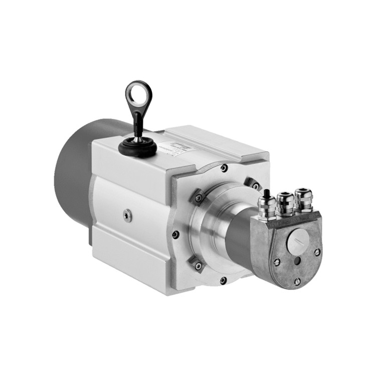
Pressure Transmitter
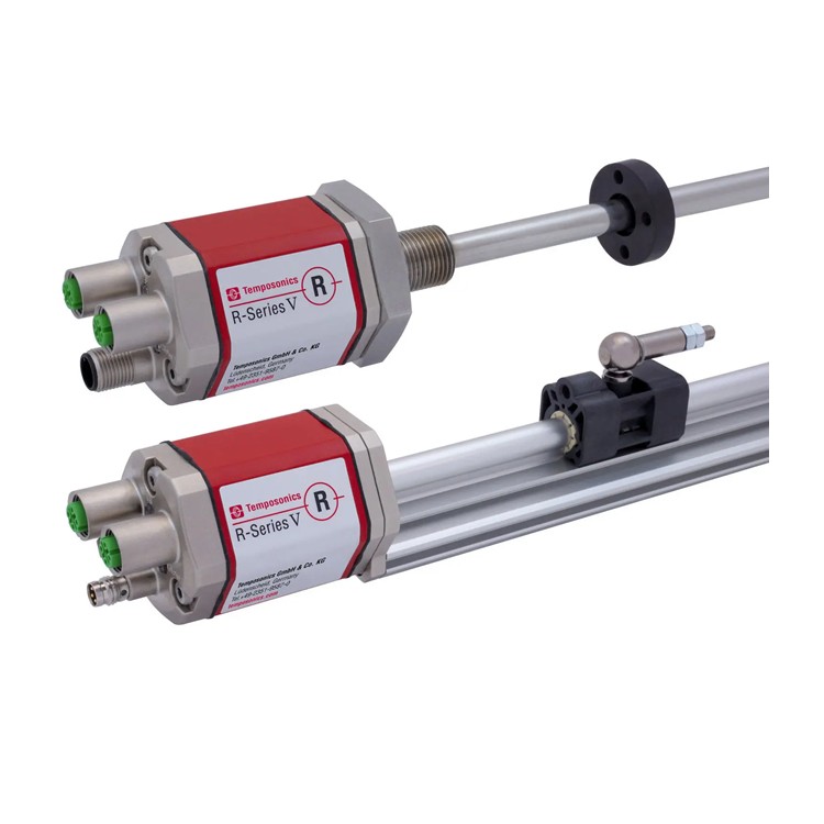
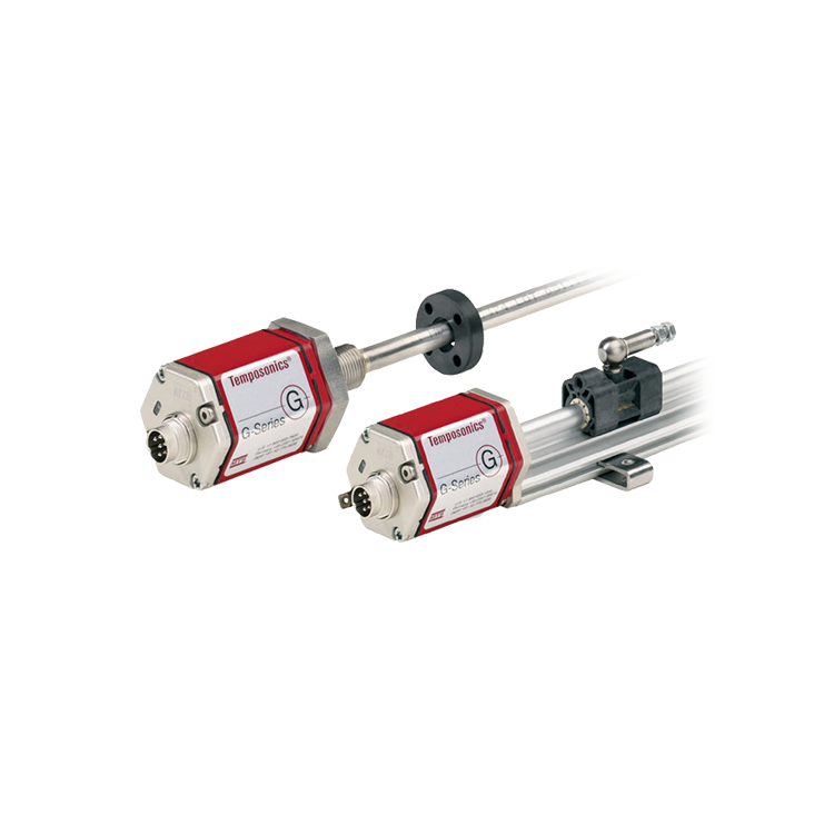
Linear Position Sensor
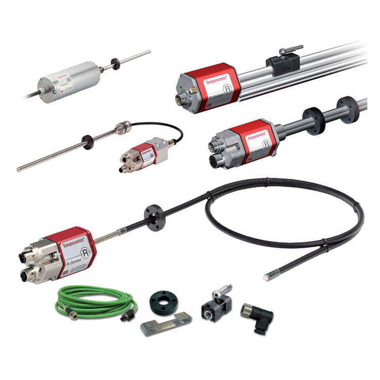
Tie-rod Position Sensor
Magnetic-Inductive Level Gauge
Magnetic-Induced Eddy Current Displacement Sensor


详情描述
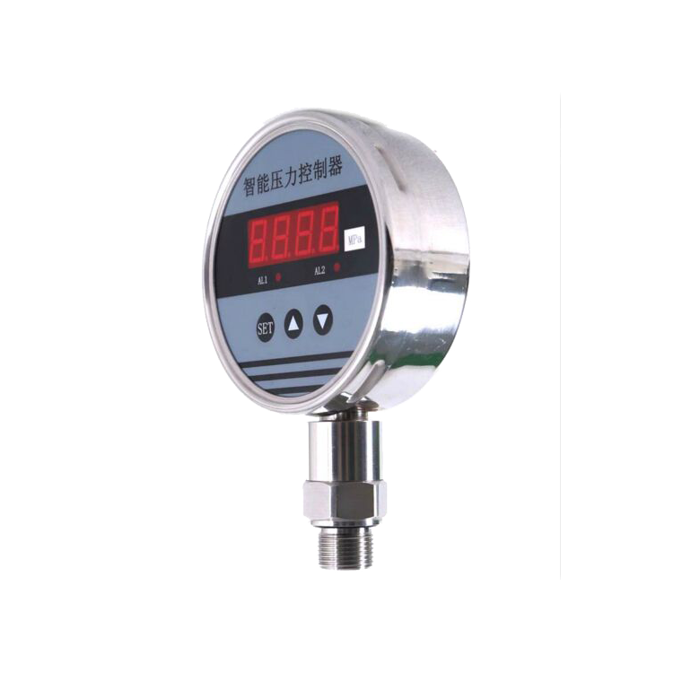
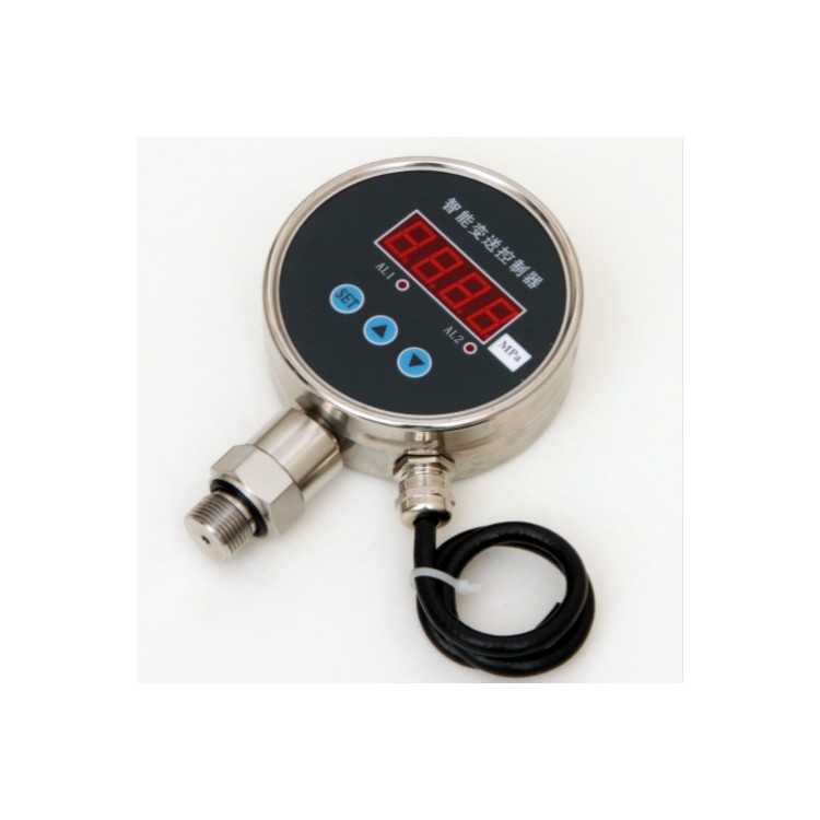
The JEF510R Pressure Transmitter Controller is a fully digital measurement and control product that integrates pressure/differential pressure measurement, display, contact control, and transmitter output, featuring an RS485 digital interface. It can be directly installed at the field pressure measurement point or mounted on a test bench control panel. It allows for on-site setting of parameters such as zero point, full scale, and contact pressure values via buttons, and also enables network, digital signal transmission, and remote setting and adjustment of transmitter parameters through the RS485 bus function. It can produce solid-state relay output interfaces for single, dual, or multi-point control as per customer requirements, and offers various signal output options including 4-20mA, 0-10mA, 0-5VDC, and 1-5VDC.
Widely applied in the automatic control fields of industries such as hydropower, metallurgy, and chemical engineering, for measuring and controlling the pressure of fluid media.
Our company leverages the technology of high-precision digital pressure gauges used in laboratories, applying it to industrial-grade pressure gauges to ensure accuracy. These gauges are particularly suitable for both field and laboratory use, enabling precise pressure measurements and verification work for general and precision pressure gauges, and other pressure instruments. They can fully replace pointer-type precision pressure gauges with superior performance.
I. Overview
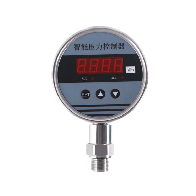
The JEF501R series pressure transmitter controller is an intelligent digital pressure measurement and control product that integrates pressure measurement, display, output, and control. This product features a full electronic structure, with a front-end oil-filled pressure resistor sensor equipped with an isolation diaphragm. It utilizes high-precision A/D conversion, processed by a microprocessor, for on-site display, and outputs one analog signal and two switch signals.
This intelligent digital pressure transmitter is versatile, easy to operate, simple to tune, and safe and reliable. It is widely used in industries such as hydropower, water supply, petroleum, chemical, mechanical, and hydraulic, for on-site measurement, display, and control of fluid medium pressure.
Section II: Features
Real-time measurement speed can be set.
11 pressure unit conversion functions
Low power consumption, longer lifespan.
Automatic Peak Value Recording
Independent two or four-way control point relay output 220V 3A; the relay switch opens when the pressure exceeds a certain value, and closes when the pressure is below a certain value. Customers can set the controlled pressure value themselves. (Default factory setting based on customer requirements for multi-way control.) Standard 4-20mA signal output (optional)
The wire harness is connected to the panel in a plug-in form, facilitating installation and removal.
Range: 0~100 MPa
Precision Grade 0.5%
Overload Capacity: 200%
Pressure Type: Gauge Pressure
Stability ≤ 0.1% / year
Power Voltage: 24VDC/220VAC
0.56" Digital Tube Display
Display Range -1999~9999
Response Time <30ms
Ambient Temperature: -20℃ to 70℃
Relative humidity ≤ 80%
Material: Stainless Steel
Pressure Connection: M20 × 1.5 (Customizable according to customer requirements)
Here is the dimension drawing:

Mechanical connection:
The pressure pipe fittings (M20*1.5) can be directly mounted on the hydraulic pipeline. In critical applications (such as severe vibration or impact), the pressure pipe fittings can be mechanically decoupled via a micro-hose.
Note: Must be installed vertically when the range is less than 100 KPa.
Electrical Connections

To prevent the impact of electromagnetic interference, the following precautions should be taken:
Keep the line connections as short as possible.
● Shielded wire
Avoid directly approaching the wiring of user devices or electrical and electronic equipment that may cause interference.
If using micro-hose installation, the housing must be grounded separately.
Wiring
Red V+, Yellow V-, Orange OUT+, White OUT-, Blue ON1, Green COM1, Brown ON2, Grey COM2
Setup Function

AL1H is the switch 1 closure value; AL1F is the switch 1 release value.
AL2H is the value for switch 2's closure; AL2F is the value for switch 2's release.
FILt This value represents the display filter coefficient, designed to prevent display fluctuations caused by pressure fluctuations. The larger the filter coefficient, the more stable the display will be, but with increased lag. Selectable range: 3~10
END Save and Exit
Note: The switching point is determined by the pull-in and dropout values. When the pull-in value is greater than the dropout value, it results in an upper limit alarm output (normally open function). When the pull-in value is less than the dropout value, it results in a lower limit alarm output (normally closed function). The difference between the pull-in and dropout values is the hysteresis of the switching point.
Set Switch Point 1 as Upper Alarm Output (Normally Open) at 4Mpa, disconnect at less than 3.95Mpa; Switch Point 2 as Lower Alarm Output (Normally Closed) at 10Mpa, connect at below 9.95Mpa.
Enter Menu: Set
AL1H=4.00 AL1F=3.95 AL2H=9.95 AL2F=10.00
● Press the "SET" button ● Display "LOCK" (prompt for password)
● Press ▲ or ▼ to enter the password "1", ● Press the "SET" key to confirm
● Use ▲ or ▼ keys to scroll up or down for menu selection (AL1H, AL1F, AL2H, AL2F, END)
● Press the "SET" button to enter the selected menu. ● Press ▲ or ▼ to change the settings.
● Press "SET" to confirm. If needed, use ▲ or ▼ keys to select other menus for modification.
● After modification, select "END" and press the "SET" button to confirm and save, then exit.
If no key is pressed within 30 seconds, the device will automatically exit the setup state without saving any modified data.
Usage Instructions:
Storage and use of instruments should be suitable at environmental temperatures of -20℃ to 70℃, and in conditions with relative humidity less than 80%.
The instrument joint should be concentric and smooth when connecting to the piping.
When connecting the instrument to the power supply, refer to the procedures in Section 5.2 for electrical connections, and only after confirming that the operation is correct, can the power be connected for operation.
Do not apply force to the instrument housing when dismantling the gauge.
Warranty
Under compliance with the usage and protection rules, the instrument is warranted for one year from the date of manufacture. Repairs after one year are handled by our company. We welcome users to contact us via letter or phone call for inquiries and suggestions at any time.


