


- AllProduct Category
-
Pressure Transmitter
Linear Position Sensor
Tie-rod Position Sensor
Magnetic-Inductive Level Gauge
Magnetic-Induced Eddy Current Displacement Sensor


详情描述
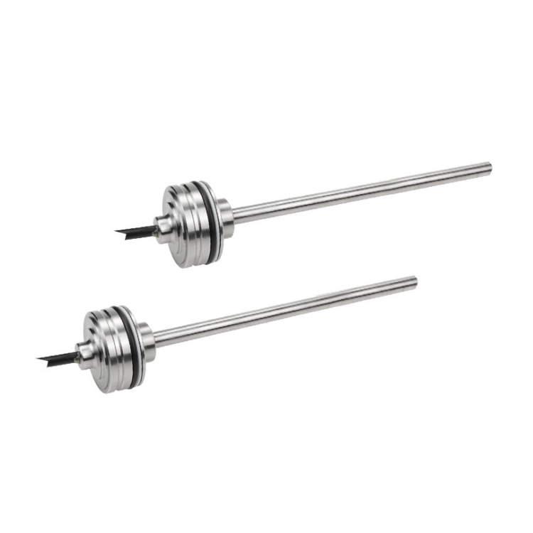
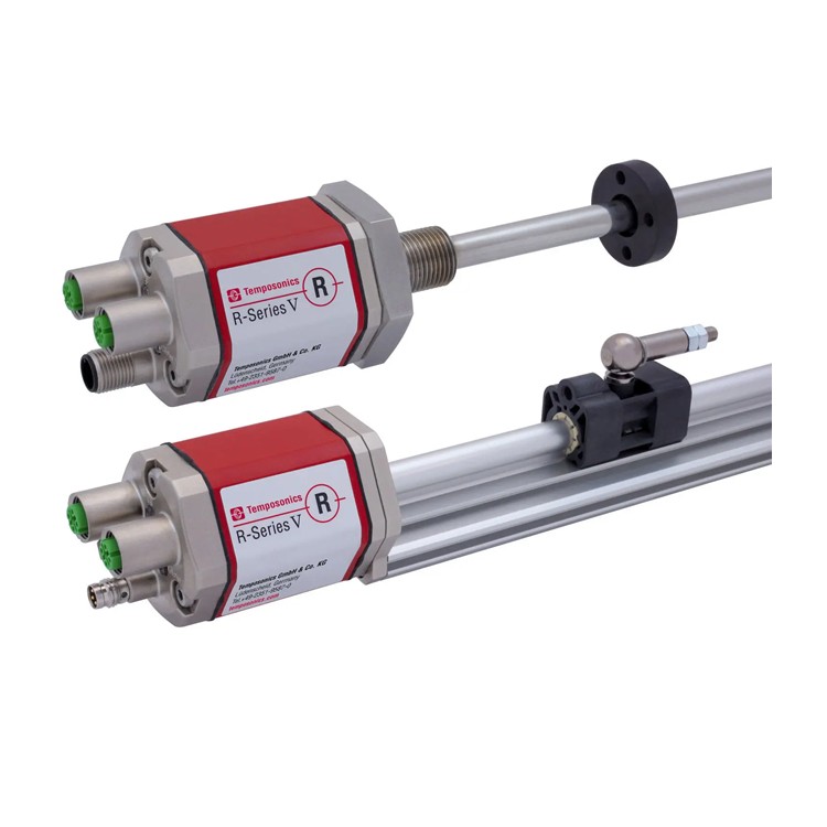
The MH magnetostrictive displacement sensor can be used unrestrictedly on multi-functional walking machinery and can replace contact-type linear sensors such as potentiometers. In high-dynamic systems, BRSEN@ sensors can be used for safety control, thereby enhancing productivity, availability, and work quality during the machine's operation. The sensors are insensitive to vibrations, shocks, dust, weather conditions, and electromagnetic interference. The MH series sensors have been successfully applied in steering cylinders for front axles and articulated frames, hydraulic jacks, and hydraulic steering systems in agricultural and construction machinery.
Simple mechanical structure
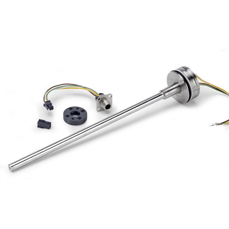
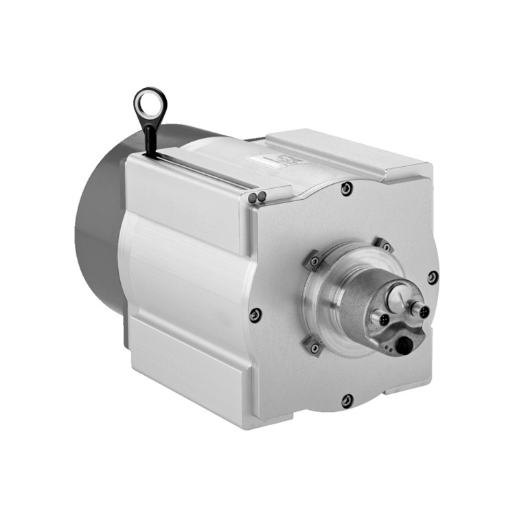
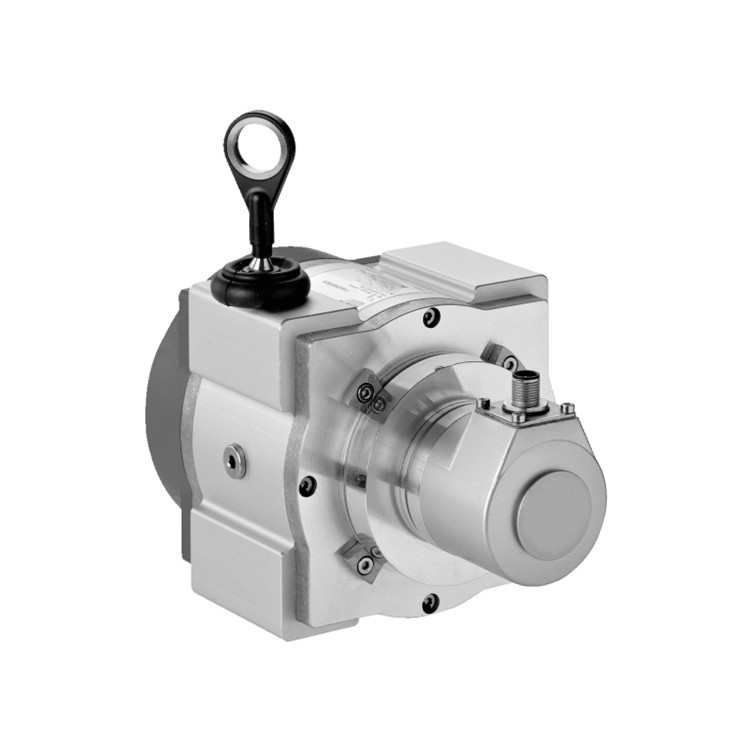
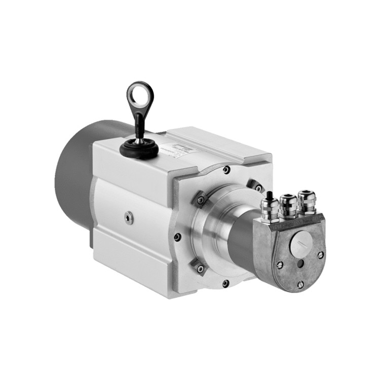
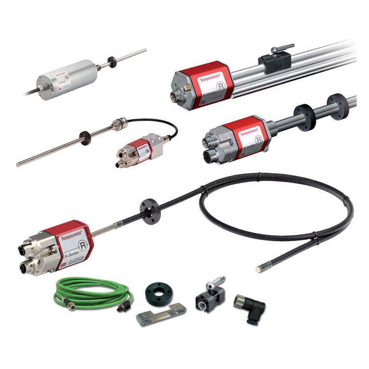
This sensor is sturdy and durable, consisting of the following main components:
① The innovative connector system can be installed in just seconds, offering great convenience without the need for welding or crimping, and boasts dust and waterproof ratings up to IP69K.
② The flange housing is equipped with an internal electronic device and a signal converter.
③ The position magnet, as a moving part, can be mounted at the bottom of the piston. This magnet is designed to move along the pressure tube, without contacting the pressure-resistant outer tube and without wear, allowing for the measurement of the actual position.
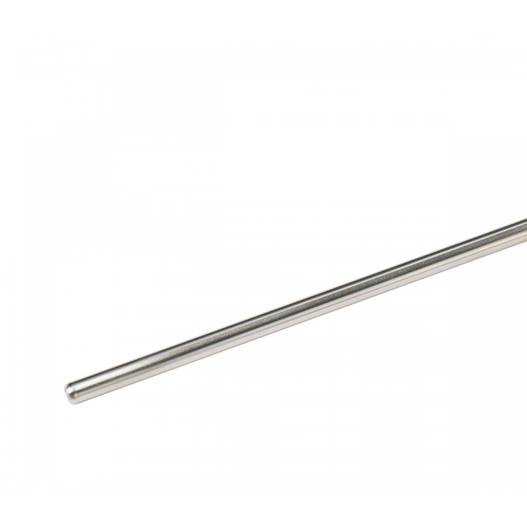
④ The pressure-resistant outer tube is placed within the bored piston rod, containing a protected magnetostrictive inductive element.
Technical Specifications:
| Parameters | Specs |
| Input | |
| Measurement Data | Linear Displacement |
| Measurement Stroke | 50mm to 2500mm, customizable as per customer requirements |
| Count measurement | One |
| Output | |
| Signal Characteristics | Bus Protocol: SAE J1939, CANopen Protocol (Compliant with CiA DS-301 V4.1, Device Configuration File DS-406 V3.1) |
| Launch Time | Typical value: 400 ms |
| Cycle Period: | CANopen:1 ms,SAE J1939:20 ms |
| Current | 4-20mA, 20-4mA, 0-20mA, 20-0mA (Low/High Load 0/250 Ω) |
| Accuracy | |
| Resolution | ±0.1mm |
| Non-linearity | ±0.1mm(50~400mm),0.02%(>400mm) |
| Repetitive Accuracy | ±0.1mm |
| Lag Tolerance | ±0.1mm |
| Last Updated | 2.0ms |
| Work Conditions | |
| Magnetic Ring Speed | At will |
| Operating Temperature | -40~105℃ |
| Humidity/Dew Point | Humidity 90%, No Condensation |
| Temperature coefficient | <30ppm/℃ |
| Impact Indicator | IEC 60068-2-27, 100g (11ms) single impact, 50g (11ms) 1000 impacts per axis |
| Vibration Index | IEC 60068-2-64, 20 g (root mean square, r.m.s.), 10 mm diameter pressure-resistant outer tube (10... 2000 Hz), excluding overall vibration frequency |
| Electrical Protection | IP67 |
| EMC Testing | GB/T 17626.2/3/4/6/8, Grade 4/3/4/3/3, Type A, CE Certified, ISO 13766, ISO 11452-2/4 |
| Structure and Materials | |
| Electronic Warehouse | Stainless Steel 304 |
| Measurement Rod | Stainless Steel 304, 8/10mm |
| Magnetic Ring | Various magnetic rings |
| Sealed | O-ring 40.87*3.53 mm NBR 80, Auxiliary Washer 42.6*48*1.4 PTFE |
| Foreign exchange pressure | Installed inside the hydraulic cylinder, it operates at 350bar/700bar (peak). |
| Installation | |
| Installation Direction | Any direction |
| Installation Type | Outer Diameter of Electronic Warehouse |
| Electrical Connections | |
| Out-of-line method | Direct cable or aviation connector |
| Input Voltage | 9-32Vdc, typically 12/24Vdc |
| Power Consumption | <1.5W, typical value ≤100mA at 12VDC; typical value ≤50mA at 24VDC |
| Polarity Protection | 30Vdc |
| Overpressure Protection | 36Vdc |
| Insulating Resistance | >10MΩ |
| Insulation strength | 500V |
The MH CAN-bus Linear Position Sensor, functioning as a slave station, complies with the Canbus (ISO 11898) protocol standard. The sensor directly converts position data into bus-oriented data and sends it to the controller. The bus interface is suitable for transmission rates below 1 Mbps. The software integrated in the sensor supports highly customizable CANopen sensor bus systems.
Pressure-resistant outer tube dimensions and installation instructions
MH Series pressure-resistant outer casing, stainless steel electronic storage, designed specifically for hydraulic system use, integrated within the hydraulic cylinder, capable of withstanding pressure up to 35MPa continuously (70MPa peak).

Installation Precautions:
Cut all sensor connections during welding!
Do not connect the grounding terminal to the piston rod or the cylinder bottom.
If sensors are installed inside the cylinder, do not weld any part of the cylinder.
If there are sensors inside the cylinder, do not weld near the cylinder.
Any part of the welding machine that comes into contact may produce current or voltage, due to the lubrication of the insulation bearing or the sliding parts of the plastic components. In such cases, the same consequences may arise.
Installation Instructions:
Install sensor housing with M5 DIN913 flat-head screws. The sensor can only be fixed in the direction of the shaft, as the screws can only contact the housing. The maximum torque on the screws is 1Nm, otherwise the sensor housing may be damaged. Additionally, apply sealant (such as Loctite Blue) to the fixed sleeve screws after installation.


