


- AllProduct Category
-
Pressure Transmitter
Linear Position Sensor
Tie-rod Position Sensor
Magnetic-Inductive Level Gauge
Magnetic-Induced Eddy Current Displacement Sensor


详情描述
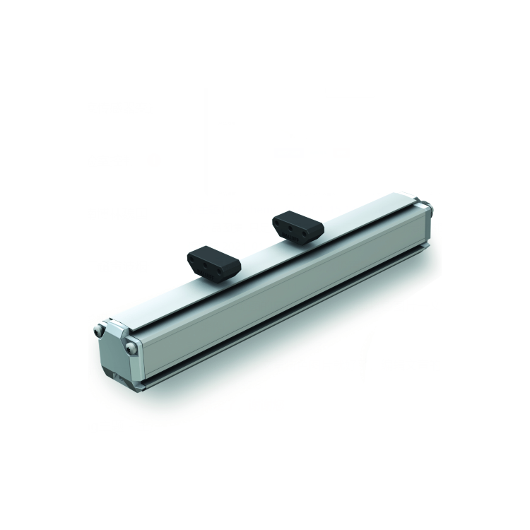
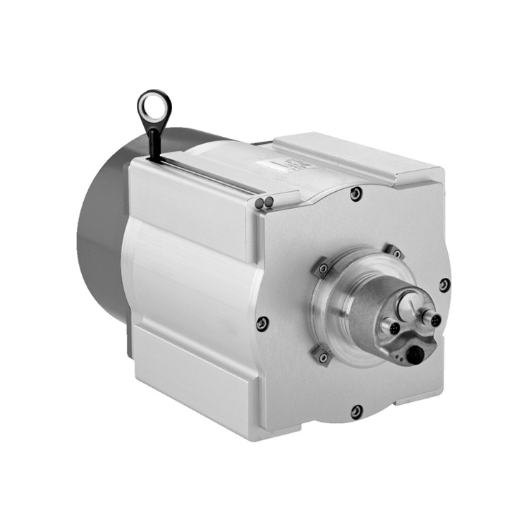
Robust and Reliable Industrial Displacement Sensor
Linear displacement measurement, value output
Contactless measurement, no wear and tear
Non-linearity less than 0.02%
■ Repeatability accuracy up to 0.001%
EMI interference suppression and CE certification
■ Simulated Output: Voltage or Current
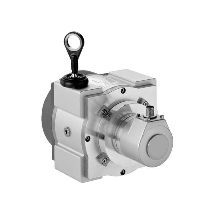
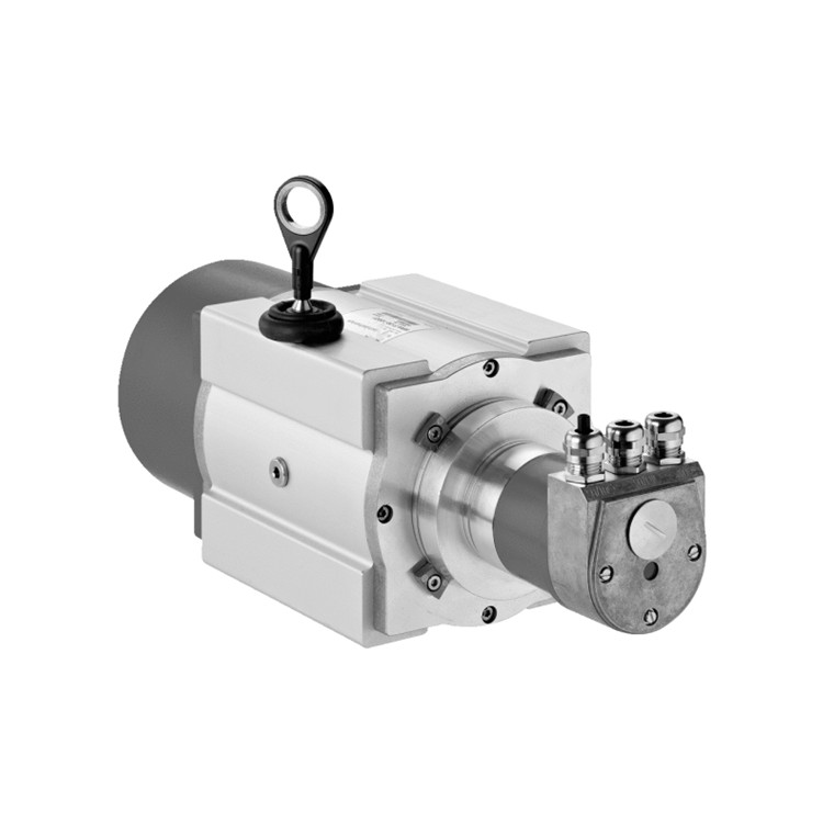
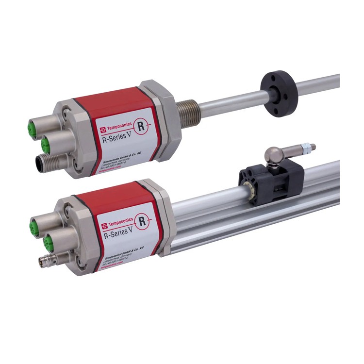
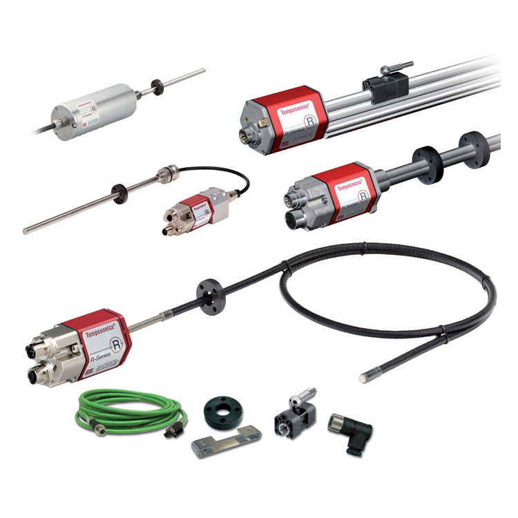
The EP-Series is a cost-effective sensor line developed by BRSEN in recent years for high-volume usage, offering a lower price point than the R-Series without compromising on functionality. The E-Series is primarily divided into the mechanical external EP, ER models, and the hydraulic integrated professional OEM product EH models. The core technology remains magnetostrictive technology, which boasts basic advantages such as contactless operation, shock resistance, interference immunity, and reliability, all of which are present in the E-Series. Therefore, it performs similarly to other series, but lacks the range of output functions and stroke options. It is widely used in general industrial automation applications.
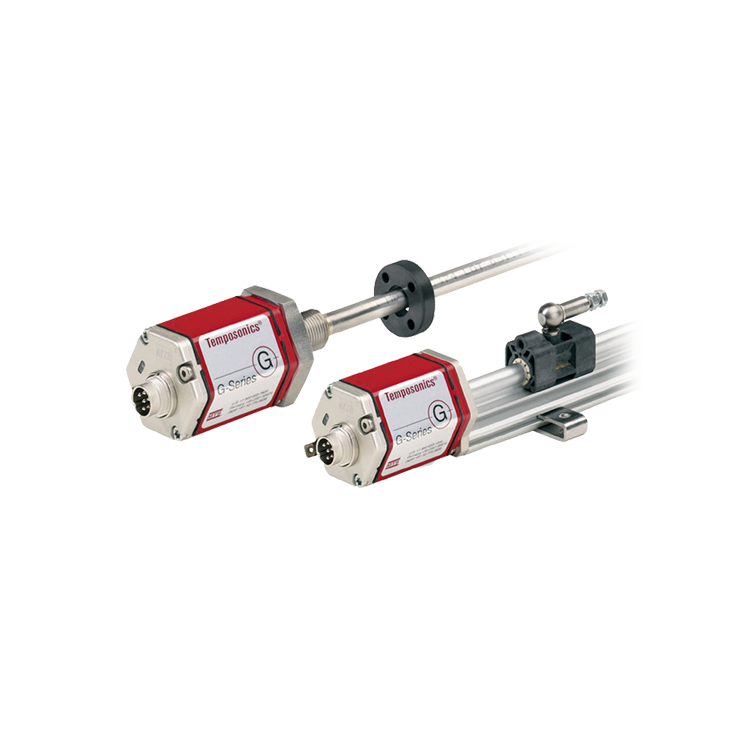
The EP type position sensor offers high repeatability precision with outputs in both analog voltage and current. Zero points and ranges are factory-set, allowing for on-site installation without re-calibration and no routine maintenance required after use. Like other BRSEN position sensor products, the EP model has passed EMC, IEC interference, vibration, and impact tests and is also CE certified. The housing complies with IP65 standards, with the option for a slider or suspended magnet installation to suit application conditions. The EP model, with its moderate price, reliable performance, and non-wearing characteristics, is one choice for replacing resistive potentiometers or LVDTs. Particularly in applications like injection molding machines, blow molding machines, and stamping machines, its cost-effectiveness is more pronounced. Experiments have shown that the non-contact EP position sensor has a significantly longer lifespan compared to contact potentiometers under harsh working conditions.
| Parameters | Specs |
| Input | |
| Measurement Data | Location |
| Measurement Range | 50 ~ 3500 mm |
| Output | |
| Voltage | 0 ~ 10 Vdc, 10 ~ 0 Vdc, -10 ~ +10 Vdc, +10 ~ -10 Vdc (Controller Low Load: > 5k ohms) |
| Current | 4 ~ 20 mA or 20 ~ 4 mA (Low/High Load: 0/500 Ohms) |
| Accuracy | |
| Resolution | Infinite (depending on the controller's D/A and power fluctuations) |
| Non-linearity | ± 0.02% full scale (fine dust 60 pm) |
| Repetitive accuracy | Full range ± 0.001% (± 2.5 pm) |
| Last Updated | >1.5 kHz |
| Fluctuation | Full Scale (F.S.) 0.01% of Full Range |
| Work Conditions | |
| Magnet Speed | At your service. |
| Operating Temperature | - 40 to +75 °C |
| Humidity, Dew Point | Humidity 90%, no condensation allowed |
| Protect | IP65 (Cable connectors must be tightly locked) |
| Impact Index | 100 g (Single Impact) / IEC Standard 68-2-27 |
| Oscillator Indicator | 15 g / 100 - 2000 Hz / IEC Standard 68-2-6 (Durability) |
| EMC Testing | Radiation EN 50081-1, Immunity EN 50082-2, EN 61000-4-2/3/4/6, Grade 3/4, Class A, CE Certified |
| Structure, Material | |
| Electronic head | Aluminum |
| Sensor Housing | Aluminum Extrusion Molding |
| Positioning Magnet | Sliding Magnet or Floating Magnet |
| Installation | |
| Installation Location | Any direction |
| Installation Type | Removable fixed clamping tabs (require M5 screws for attachment) |
| Electrical Connections | |
| Connector selection | 6-Pin DIN Connector or Straight Cable |
| Input Voltage | +24 Vdc (-15 / +20%) |
| Power consumption | 50 - 100 mA (as per range) |
| Fluctuation | < 1% peak |
| Electrical impulse quantity | 500 V (DC ground to machine ground) |
EP Type Shell Dimensions and Installation Instructions

Description: (1) The number of fixing clips required for installation corresponds to the range. It is recommended to add one clip for every 500mm increase in range.
(2) The EP series products use floating magnets for position measurement: directly mounted on moving parts, not in contact with the sensor. Allows ±3mm lateral offset and up to 10mm vertical gap.
Sensor wiring method
When connecting aviation connectors, define by the pin and the corresponding wire color.
Waterproof connector directly exiting the wire, defined by wire color
D60 Connector Pin Arrangement (for Sensor Head)

| Needle size | Line color | Definition |
| 1 | Gray | Analog Signal Output |
| 2 | Powder | Signal Ground |
| 3 | Yellow | Communication Interface (+) |
| 4 | Green | Communication Interface (-) |
| 5 | Brown | +24VDC(-15%/+20%) |
| 6 | White | Direct Current Power Supply接地 |


