

- AllProduct Category
-
Pressure Transmitter
Linear Position Sensor
Tie-rod Position Sensor
Magnetic-Inductive Level Gauge
Magnetic-Induced Eddy Current Displacement Sensor


详情描述
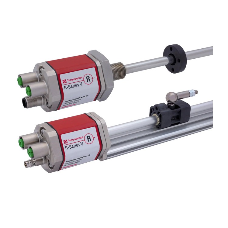
Linear value measurement integrated within the hydraulic cylinder
Overall stainless steel round tube sensor
Contactless measurement, durable and long-lasting
Industrial sensors for harsh environments, EMC interference resistance, and CE certification
High Precision: Linear Deviation Less Than 0.02%
■ Repeated accuracy up to 0.001%
High resolution up to 5 pm
Direct 24/25-bit SSI output (Gray code or binary code)
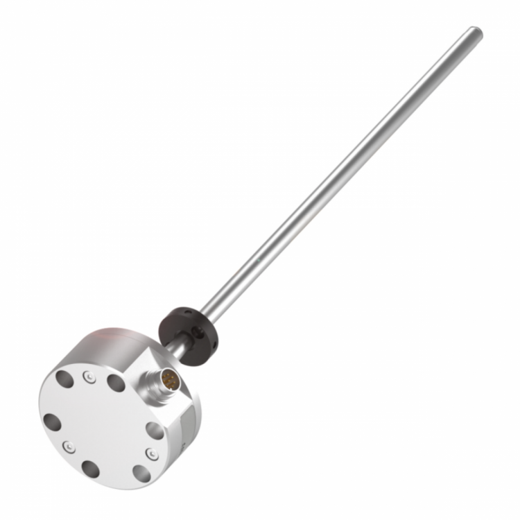
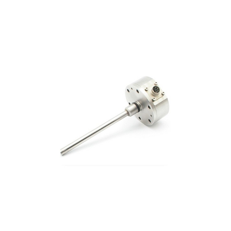
GB Type Displacement Sensor
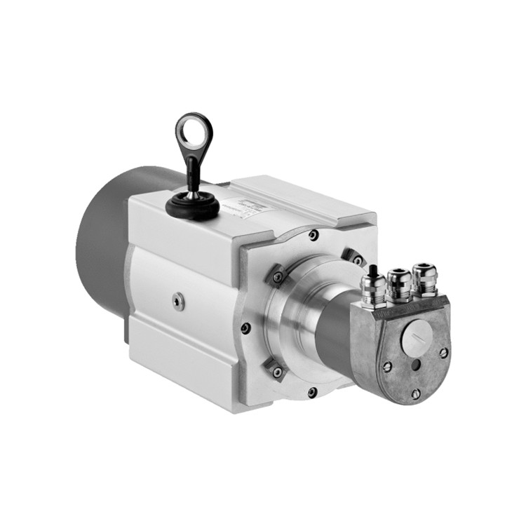
These sealed pressure sensors are specifically designed for hydraulic cylinder installation applications, particularly suitable for U-shaped head hydraulic cylinders or those with limited space.
For the widely used standard hydraulic cylinders, the GB type sensor is a good choice. A magnetostrictive position sensor, combined with a high-quality cylinder body and control valve, forms a drive system that can meet the technically high-standard requirements of the machining industry.
The GB type sensor's interface meets the SSI standard requirements for value rotation sensors. Its positional values are encoded into 24 or 25-bit binary or Gray code and transmitted very quickly to the controller via a serial RS422 standard format. In a closed-loop control system, SSI provides an effective synchronous setting. The controller clock controls data transmission.
| Parameters | Specs |
| Input | |
| Measurement Data | Location |
| Measurement Range | 50 - 5080 mm |
| Output | |
| Interface | SSI (Serial Synchronous Interface), RS-422 communication format |
| Data Format | Binary or Gray code |
| Data Length | 24 or 25-bit (as per requirement) |
| Accuracy | |
| Resolution | 5 / 10 / 20 / 50 / 100 um |
| Linearity | Full scale ± 0.02% (Fine Dust 60 um) |
| Repeatability accuracy | Full scale ± 0.001% |
| Temperature Coefficient | <15 ppm°C |
| Work Conditions | |
| Magnet Speed | Any |
| Operating Temperature | - 40 to +75 °C |
| Foreign exchange pressure | 350 bar / 700 bar (Peak) |
| Protect | IP67 (Connector must be tightly sealed) |
| Impact Indicator | 100 g (Single impulse) / IEC Standard 68-2-27 |
| Oscillator Indicator | 15 g / 100 - 2000 Hz / IEC Standard 68-2-6 (Durability) |
| EMC Testing | Radiation EN 50081-1, Immunity EN 50082-2, EN 61000-4-2/3/4/6, Grade 3/4, Class A, CE Certified |
| Structure, Material | |
| Electronic Head | Stainless Steel 1.4305 / AISI 303 |
| Sensor Rod and Flange | Stainless Steel 1.4301 / AISI 304 |
| Position Magnet | Circular Magnet |
| Installation | |
| Installation Location | Any direction |
| Installation | Sealed Flange 0 18h6, 6 bolt holes (ISO 4762 standard) |
| Electrical Connections | |
| Connector selection | 7mm DIN Connector or Direct Cable (PUR Cable 3 x 2 x 0.25 mm², Φ7.9mm) |
| Input Voltage | +24 Vdc (-15 / +20%) |
| Power consumption | 50 mA (as per scale) |
| Fluctuation | < 1% Peak |
| Electrical shock volume | 500 V (DC grounded to machine ground) |
GB Type Shell Dimensions and Installation Instructions

Installation is simple at any location and requires minimal space.
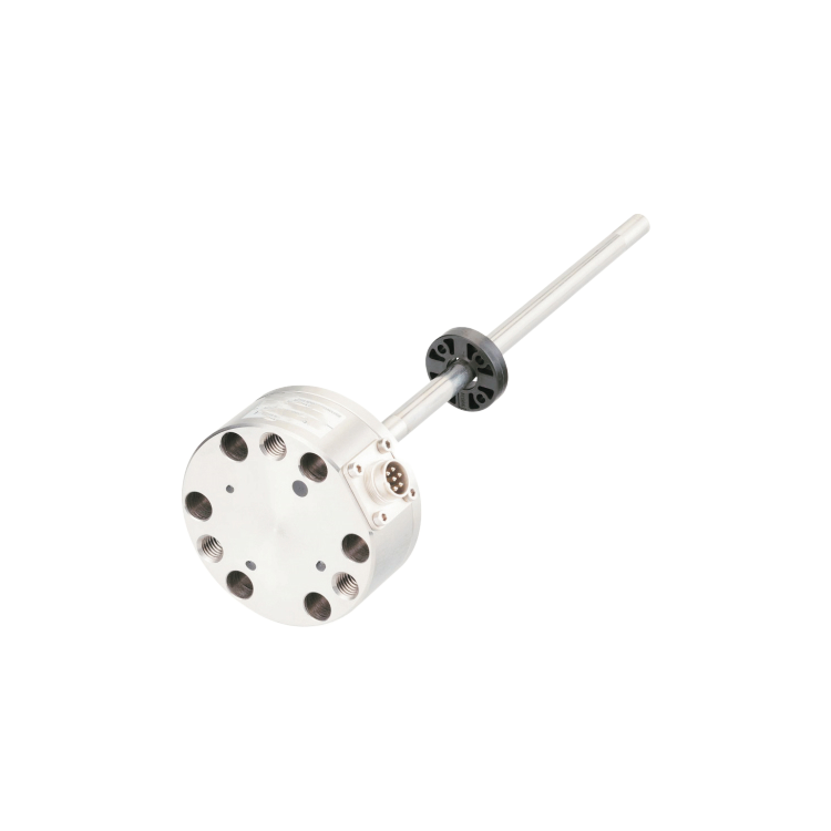
The pressure-resistant stainless steel round tube with an installation flange is secured through the threaded holes of the electronic head with 6 M6*16* A2-70 (ISO4762) screws. A tight seal is achieved using a 15*2 O-ring and a locking ring.
Hydraulic Installation Diagram Examples
Utilize a rod sleeve (such as Teflon) to prevent friction between the magnet and the sensor rod. The hole in the piston rod depends on factors like hydraulics and speed. The hole diameter must not be less than 13mm and should not exceed the peak pressure of 700bar.

Position Magnet
To measure position, secure the magnet using non-magnetic mounting devices (screws, supports, etc.). When the carrier is made of ferromagnetic material, ensure to install the magnet with a non-magnetic shim of 5mm thickness and non-magnetic screws. Note the small installation dimensions shown in the illustration on the right.

Sensor wiring method
When connecting aviation connectors, define by the pin and the corresponding wire color.
Waterproof connector directly exiting with wire color definition
D70 Connector Pin Arrangement (Facing the Sensor Head)

| Needle size | Line Color | Definition |
| 1 | Ash灰色 | Data (-) |
| 2 | Powder | Data (Plus) |
| 3 | Yellow | Clock (+) |
| 4 | Green | Clock (-) |
| 5 | Brown | +24VDC(-15%/+20%) |
| 6 | White | Direct Current Power Supply Ground |
| 7 | No engagement |
If the installation process may damage the straight-through cable, please opt for the connector connection method. The electronic part of the sensor and the straight-through cable are both fully embedded and fixed within the circular disk of the electronic head, making repairs to the electronic module difficult. In case of any issues, the entire sensor must be replaced.


