
- AllProduct Category
-
Conveying Equipment
Brush Sweeper
Distribution Equipment
Industrial Equipment
Hydration Bag
Wall Saws


Recommended Products
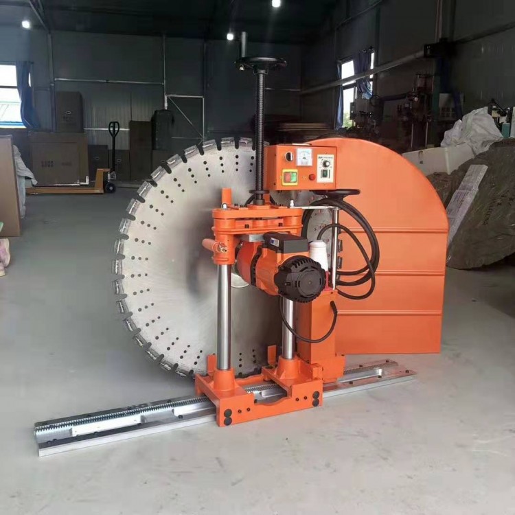
Wall Saws (Construction Site) - Concrete and Reinforced Steel Wall Cutting Machines
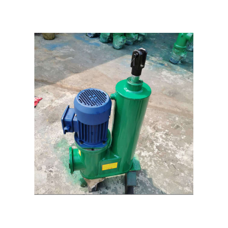
3kW Straight Electric Actuator, Hydraulic Cylinder, Coal Cutting Equipment Matching Hydraulic Push Rod
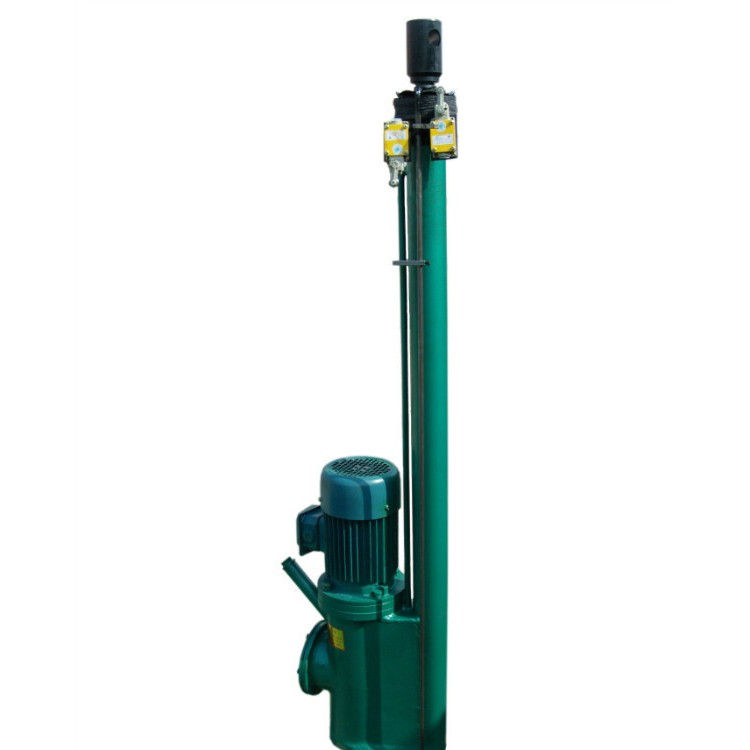
卸灰阀配套推杆 DYTP-700-400 Parallel Hydraulic Push Rod
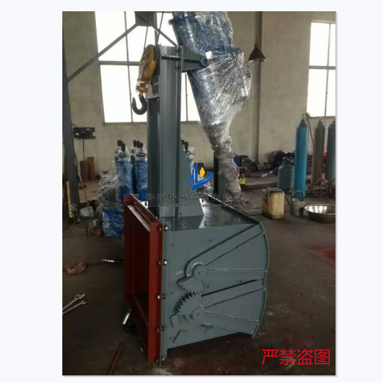
Electrical Rugged Gate Valves, Electro-hydraulic Actuated Rugged Gate Valves, Various Diameter Ash Discharge Valves
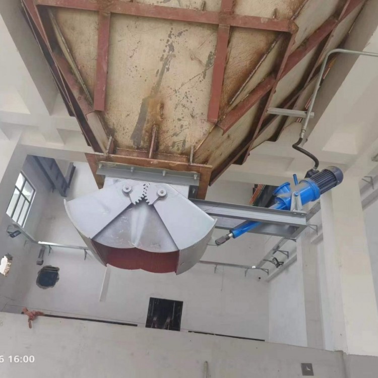
DSZ-600 Electro-hydraulic Butterfly Gate, Discharging Equipment, Double-Leaf Electric Valve
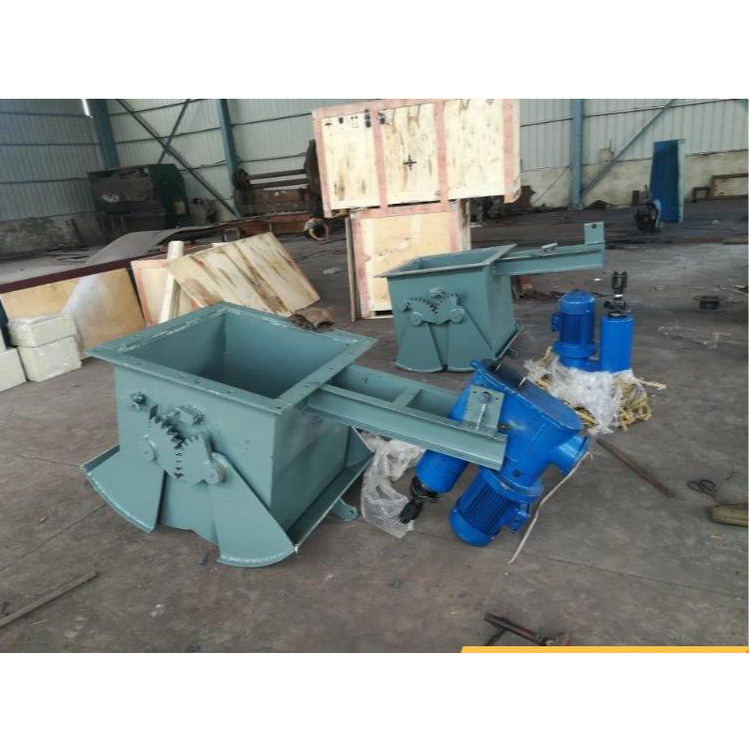
Material Storage Gate, Electro-hydraulic Scissor Gate, Mine Electric Push Rod Discharge Valve
详情描述
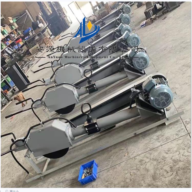
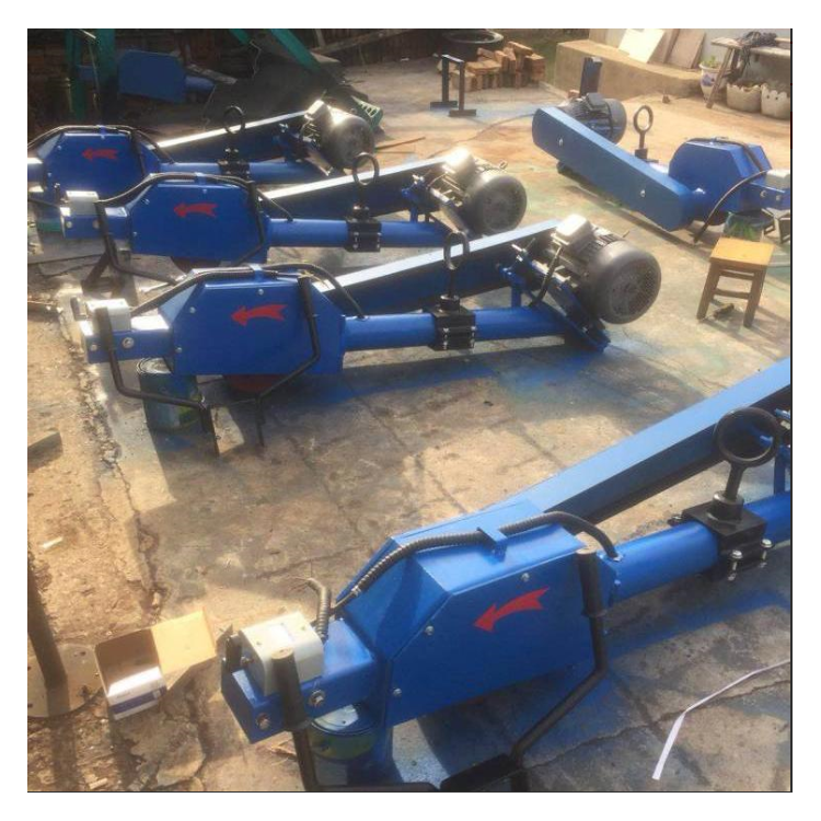
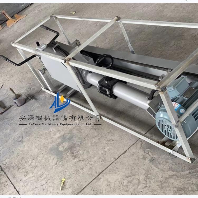
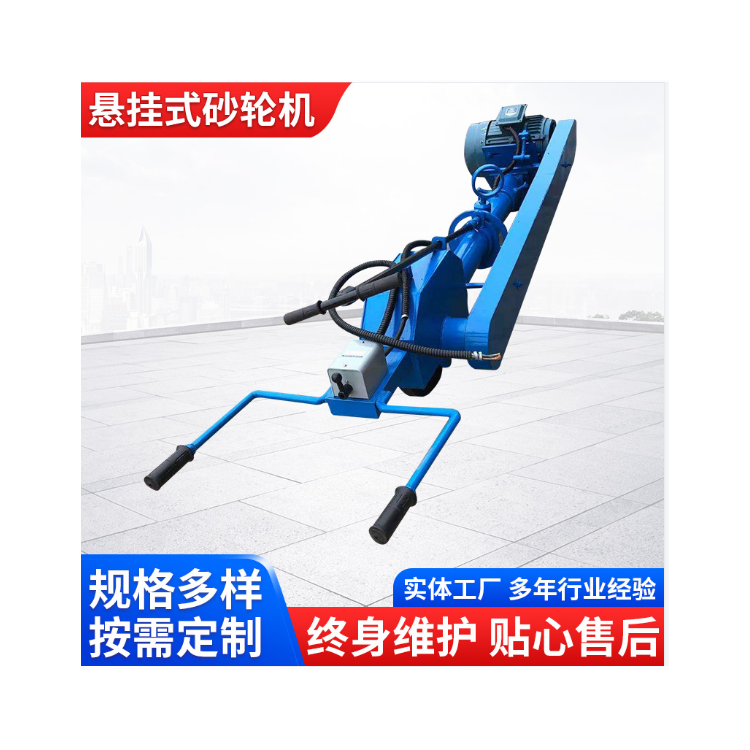
Handheld Swing Arm Grinding Wheel Machine M3140 Suspended Grinding Wheel Machine Hanging Grinding Wheel Machine
Hand-held swing arm suspended grinding wheel machine, featuring a vertical shaft fixed to the ground base.A rotating mechanism supported by a vertical shaft, a lifting mechanism, a grinding wheel mechanism, a belt tensioning mechanism, an operating handle and a protective screen mounted on the grinding wheel mechanism. The rotating mechanism includes a set of rotating sleeve 2 mounted on the vertical shaft 1, which can rotate around the shaft. A support bearing (not shown in the diagram) is provided between the rotating sleeve and the rotating surface of the shaft for smooth rotation. The transverse arm 9 of the rotating mechanism is connected to the rotating sleeve 2 via the lifting mechanism, with its other end welded to a tube 19. Inside the tube is a central shaft 11 supported by thrust and ball bearings 24. The lower part of the central shaft is connected to a connecting bracket 13 via a transverse shaft 12, which in turn connects to the grinding wheel frame 14 of the grinding wheel mechanism. A dust cover 23, secured with nuts, is mounted above the tube to prevent the shaft from being eroded by rain and dust. The rotating mechanism is responsible for the front, rear, left, and right swinging movements and circular motion around the vertical shaft, meeting the needs of large workpiece processing. The lifting mechanism features a connecting plate 22 welded to the rotating sleeve 2, with two plates, each having a single "U"-shaped slot on the top side. Two inclined parallel rods 6 and a parallel transverse arm 7 are hinged at both ends to the connecting plate 22 and the transverse arm 9, forming a four-bar linkage. A cross head nut 5 is inserted into the "U"-shaped slot of the connecting plate 22 before welding. A screw 4 with a handwheel 3 is threaded onto the cross head nut 5, and its head is connected to a connecting block 21 welded to the parallel transverse arm 7, forming a hinge. The screw 4 is supported by a bearing 24, with the outer end connected to a nut 23. When the handwheel 3 rotates the screw 4 relative to the cross head nut 5, the screw moves axially while rotating, lifting or lowering the four-bar linkage via the cross head 25, thus raising or lowering the transverse arm 9 and the grinding wheel mechanism to enhance the machine's adaptability. The grinding wheel mechanism is powered by an electric motor 8, driving the grinding wheel 16 mounted on the grinding wheel frame 14. Since the grinding wheel frame is fixedly connected to the connecting bracket, the motor and grinding wheel can rotate synchronously with the central shaft. The motor's output shaft pulley and the grinding wheel's pulley are connected by a belt 15 to transmit power and drive the grinding wheel, using a V-belt. The operating handle 18 is welded to the grinding wheel frame 14 and must be at an angle suitable for easy hand operation. To ensure the safety of the operator, a protective screen 17 is mounted below the operating handle to prevent injury from flying debris due to a broken grinding wheel. The motor's base 20 and the grinding wheel frame 14 are equipped with a belt tensioning mechanism, which is hinged at one end to the motor base and connected to an adjusting bolt 10 for adjusting the belt tension, ensuring stable performance and ease of adjustment. During operation, the operating handle 18 can be swiveled left and right to make the grinding wheel mechanism swing left and right around the vertical shaft 1. Turning the handle 18 to face the operator allows for forward and backward movement, making the grinding wheel mechanism swing forward and backward around the vertical shaft 1. Lifting the handle 18 up and down causes the grinding wheel mechanism to lift and lower around the transverse shaft 12, and pushing the handle can also rotate the grinding wheel mechanism around the vertical shaft 1 for circular motion, allowing for multi-directional finishing of castings.