


Grouting curtain is a type of grouting technique. This technique involves using hydraulic or pneumatic pressure to inject solidified grout through specialized grouting holes into designated rock and soil layers at a designed concentration. This is done to fill in cracks or voids within the rock and soil mass, enhancing the physical and mechanical properties of the grouted object, and meeting the needs of various projects. Depending on its function, it can be categorized into waterproofing grouting and reinforcement grouting. Waterproofing grouting is a widely used method to improve the waterproofing capabilities of various foundations. Also known as waterproofing grouting, it involves injecting grout into boreholes at reasonable intervals, causing the grout bodies in each hole to overlap, forming a concrete waterproofing wall similar to a curtain, thereby cutting off water flow and achieving the purpose of waterproofing and leak prevention.
One, Grouting Reinforcement Plan
Gating sequence
1) Drilling and grouting are performed from the outer circle inward. In the same circle, grouting is divided into two sequences from top to bottom. The first sequence holes are mainly grouted according to the quantitative grouting principle, while the second sequence holes are mainly grouted according to the pressure grouting principle.
2) First, inject grout into the holes on the tunnel's roof slab, then into the sides of the tunnel roof, and finally into the bottom slab holes.
3) Injection operations for a single hole section should generally be conducted continuously until completion, avoiding interruptions as much as possible. Mechanical failures, power outages, water shortages, and equipment issues should be minimized to prevent forced interruptions. For intentional interruptions such as intermittent injections and preventing leakage, the hole should be cleared to the original design depth before re-injection.
4. Gating Materials
The casting material mainly consists of a single liquid slurry of ordinary silicate cement, with the auxiliary use of a double liquid system of ordinary silicate cement and water glass.
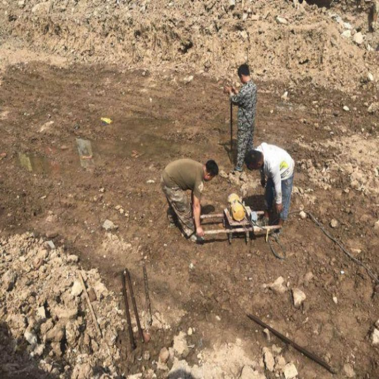
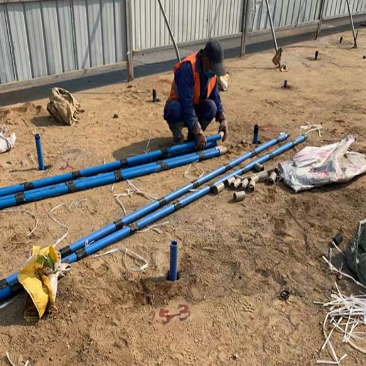
5. Drilling Grouting Technique
First, drill a hole 2 meters deep with a diameter of Φ150mm, and install a consolidation pipe with a Φ140mm opening at a depth of 3 meters.
(2) Drilling a Φ90mm grouting hole through the orifice pipe, initiate grouting operations upon reaching the grouting section depth.
(3) Utilize the forward progressive grouting technique for drilling grouting work, with grouting sections of 3 to 5 meters in length. This means drilling 3 to 5 meters, then grouting once, followed by drilling another 3 to 5 meters for grouting, and so on, in a cyclic manner until the grouting of the hole is complete.
(4) If sudden water inrush or hole collapse occurs during drilling, stop drilling immediately and proceed with grouting.
6. Gating Standard
1) Single-hole grouting completion standard
The grouting pressure is gradually increased to the final design pressure, and grouting is continued for more than 10 minutes; the inflow rate of grout at the end of grouting is less than 20L/min.
2) End of section standard
All grouting holes have met the single-hole completion conditions; inspected holes have no slurry flow, good hole formation, no collapse or leakage; the water consumption for hole inspection is less than 0.02 L/m.min; core extraction from the inspected holes shows full浆液 filling, and the solidified physical and mechanical properties meet the design specification requirements; the effective grouting range exceeds the design value.
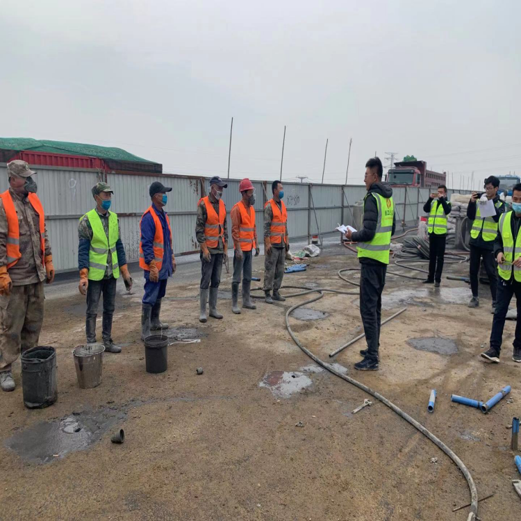
7. Gating Control Process
During the grouting process, the grouting pressure gauge must be monitored at all times. If the grouting pressure rises rapidly, stop the grouting, inspect the grouting equipment and pipelines, analyze the cause, and rectify the fault before resuming the grouting.
Primarily controlled according to design requirements, if the grouting amount is large and reaches 1.5 times the design grouting amount without reaching the design final pressure, intermittent grouting is adopted. Grout for 5 minutes, stop for 5 minutes, then grout for another 5 minutes, stop for 5 minutes... Repeat this process until the total grouting amount reaches twice the design grouting amount, then stop grouting in this hole.
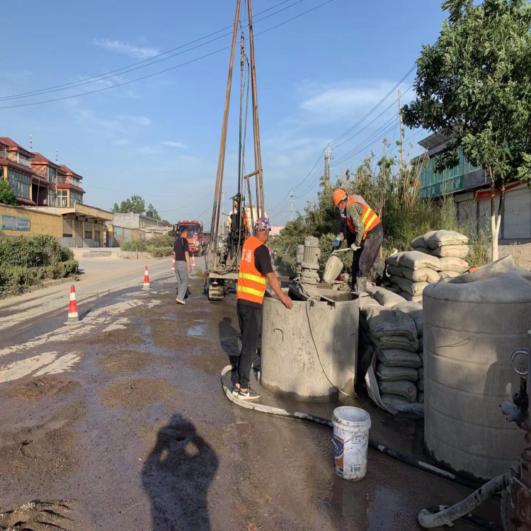
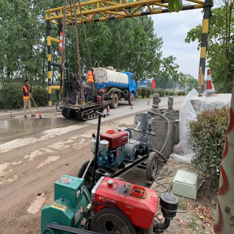
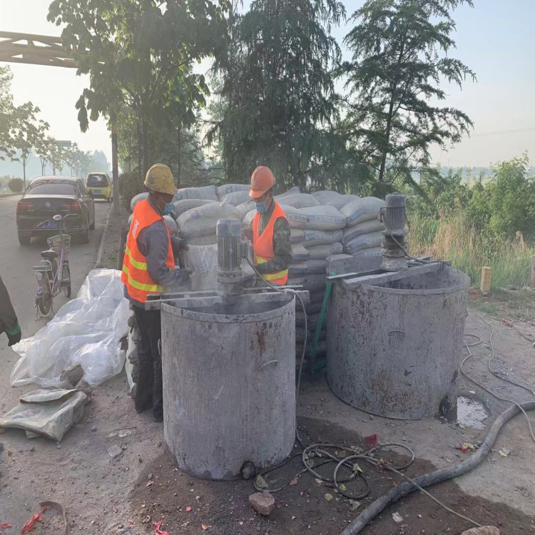
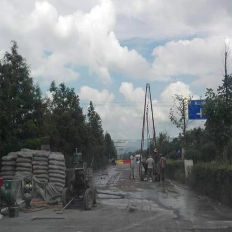
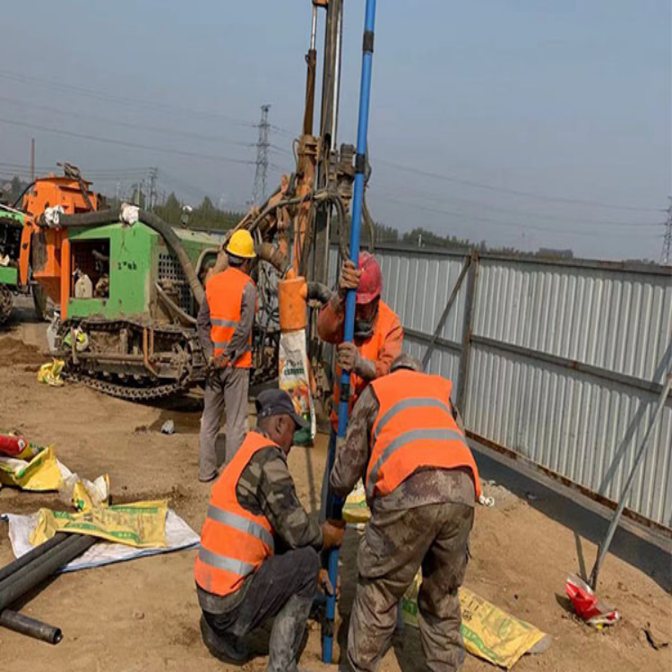
II. Advanced Grouting Construction Status
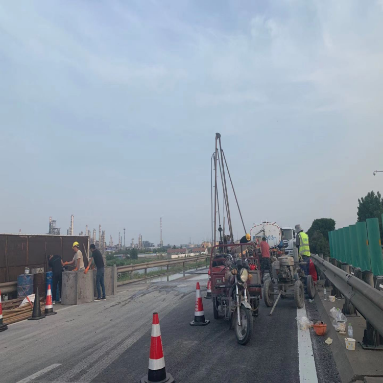
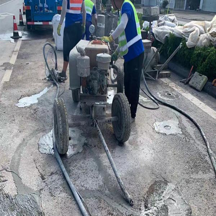
The machinery investment for this grouting cycle mainly includes: two YG-70A full-hydraulic geological drilling rigs initially invested, followed by an analysis of efficiency during the construction process. These rigs were slow in drilling through fractured rock layers with high water output, and positioning and dismantling the drill rods and tools were time-consuming and labor-intensive, leading to low construction efficiency. After analysis, a full-hydraulic crawler Z-GP150 multi-functional drilling rig was adopted, with the two geological drilling rigs serving as backups, significantly improving drilling speed and construction efficiency. The grouting pumps include two KBY-70/80 high-pressure dual-fluid grouting pumps, two Black Typhoon high-pressure grouting pumps, and two self-made 1.2m slurry storage drums. The slurry mixing is done by mechanical mixers at the entry mixing station, and then transported to the construction site by concrete trucks after the holes are drilled. This includes 4 T-type mixers, 30 D25mm—Q16Mpa×10 high-pressure grouting pipes, and other corresponding grouting equipment.
Grouting reinforcement commenced with the arrival of the grouting equipment on July 5th. Drilling for inspection holes began on September 15th, and the drilling of inspection holes was completed on September 16th. During the construction, 192 grouting holes, 2 water diversion holes, and 5 inspection holes were made. The construction followed the order from top to bottom, starting with the outer circle before moving to the inner circle. Grouting was carried out primarily with a fixed pressure principle, with quantity as a secondary consideration.
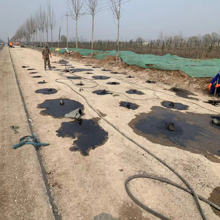
From the overall situation of the grouting drilling, the surrounding rock in front of the face is generally broken, with well-developed groundwater and high groundwater level, posing a risk of high-pressure water inrush. The rock mass in this section consists of limestone and marlstone, is fragmented, and has well-developed joints and fissures. Water infiltration from the surface is easy, and there is a significant increase in water output during rainy days, with small fissures and cavities present. During the deep grouting in the upper section of the face, water leakage and subsidence occurred at the arch roof within a 10-meter range behind the face, with initial support deformation, spalling, and falling rocks. To prevent more severe compressive deformation of the arch roof and to effectively control the grout, radial reinforcement was carried out within a 10-meter range behind the face from September 07 to September 11. After the radial reinforcement was completed, grouting reinforcement for the front face was then performed.
Section 3: Grouting Volume Distribution
This grouting project commenced on July 5, 2012, and concluded on September 16, 2012. A total of 192 grouting holes were completed, with a total grouting volume of 7,326.8 m³, including 4,270.28 m³ of single-component slurry and 3,056.52 m³ of double-component slurry. The distribution of grouting volume across the full cross-section revealed that the left side required 3,974.5 m³, the right side needed 3,352.3 m³, the lower half 2,945.8 m³, and the upper half 4,381 m³. Observing the distribution, the left stratum was relatively fractured with more developed fissures in the surrounding rock than the right, necessitating a higher grouting volume. After initially grouting the upper half, due to the upward migration of slurry during grouting, the lower half required less grouting volume to be completed, effectively improving grouting efficiency and accelerating construction progress while controlling the effective grouting reinforcement area.
IV. Grouting Effect Inspection
A total of 5 inspection holes were designed in this cycle, each with a depth of 30 meters. The inspection results show no cave-in or drill jamming during the drilling process. The final water output from all 5 inspection holes met the design requirements. The arch crown inspection hole had almost no water up to 24 meters, with increasing fissure water after that, with a final water output of 0.3 m/h. The left inspection hole had no water up to 30 meters, with increasing fissure water after 23 meters, with a final water output of 0.35 m/h. The right inspection hole had no water up to 21 meters, with increasing fissure water after that, with a final water output of 0.29 m/h. The lower inspection hole had almost no water up to 20 meters, with increasing fissure water after that, with a final water output of 1.6 m/h.
From the drilling and inspection holes, it is evident that the full-section grouting has achieved the anticipated goal of reinforcing the strata, with all indicators basically meeting the design requirements.
1. Inverse calculation of slurry filling rate
Calculation of the formation filling rate based on ΣQ = Vnα(1+β). Total grouting volume ΣQ = 7326.8 m³; volume of solids Vn; α — formation porosity, 10%; β — slurry loss rate (%), 20%.
The slurry filling rate calculated is α=1.4, exceeding the design value. Two reasons for this are: 1) There are small fissures and cavities within the reinforced formation area, with a high porosity of 30%~35%; 2) Some slurry has escaped the designed reinforcement area.
Five, Some Realizations
1. The full-section curtain grouting commenced on July 5, 2012, and concluded on September 16, 2012, spanning 71 days. The drilling and grouting were strictly carried out according to the design drawings and subjected to effect inspections. Rigorous process control and management were implemented, with bold innovation and exploration in the grouting technique for the water-rich fractured marlstone. This ensured the quality of the grouting. The grouting effect in front of the heading for 28 meters was relatively ideal, with stability and water output controlled within the design requirements.
2. It is necessary to perform effective radial grouting reinforcement on the strata behind the face within a certain range during the full-section grouting in the future, to prevent the grout from flowing backward during the grouting process, causing initial support deformation and affecting construction safety, as well as delaying the project timeline.
3. The geological conditions revealed through drilling indicate the presence of relatively wide cracks measuring 10-20cm and small溶隙、溶腔 of up to 50cm. Furthermore, based on the on-site construction situation, for such strata, grouting is first carried out to specifically seal water, followed by reinforcement of the strata to ensure it has a certain degree of strength and stability.
4. The grouting material primarily consists of a single-component slurry made from ordinary Portland cement, with an auxiliary use of a dual-component slurry made from ordinary Portland cement and water glass. The initial grouting volume is large, but it decreases with the deepening of the boreholes as the formation is reinforced and compacted. The pressure rises rapidly, especially after 24 meters where the development of small fissures is stronger. Due to the long gel time and low solidification rate of the single-component slurry made from ordinary portland cement, it has poor resistance to water dispersion under high-pressure dynamic water action. The dual-component slurry made from ordinary portland cement and water glass, due to its low strength and injectability, has a limited diffusion range and poor stability in the formation. Consequently, whether to use the single-component slurry made from ordinary portland cement or the dual-component slurry, the grouting effect is poor in the later stages. Whether to adopt ultra-fine cement or other grouting materials in the later stages is a consideration worth pondering.