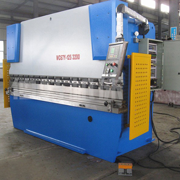


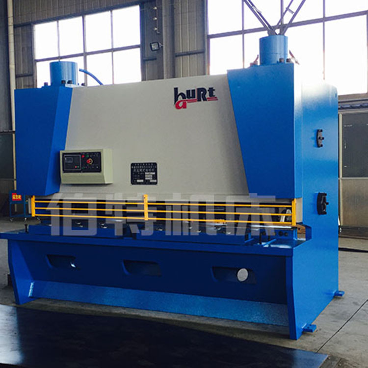
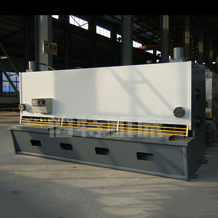

Hydraulic plate bending machine main features and applications:
WC67Y hydraulic plate bending machine, featuring steel plate welded structure and vibration aging to relieve stress. The machine tool boasts excellent rigidity and stability. The entire machine frame has good rigidity, operates smoothly, and is easy to handle. Through the coordinated control of the bending machine's digital display and the hydraulic system, it achieves ideal bending results.
Hydraulic Plate Bending Machine Technical Description:
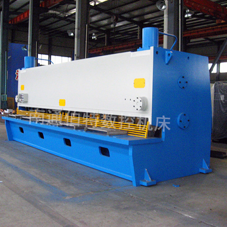
Full steel welded structure, vibration-damping, high mechanical strength and rigidity
Hydraulic power transmission, smooth and reliable.
Mechanical stopper, shaft synchronization, high precision.
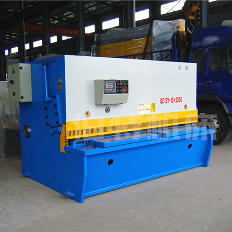
The backstock distance and upper slider stroke are electrically adjustable with manual fine-tuning devices and digital display. The upper mold is equipped with a deflection compensation mechanism. For models of 250 tons or more and over 4000mm in length, a lower deflection compensation mechanism is used.
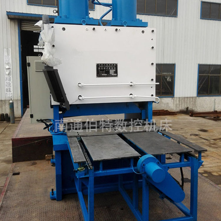
Main components and structure of machine tools
1. Slider section: Utilizes hydraulic transmission. The slider section consists of sliders, cylinders, and a mechanical stop fine-tuning structure. The left and right cylinders are mounted on the machine frame, and the pistons (shafts) are driven to move the sliders up and down through hydraulic pressure. The mechanical stops are adjusted according to the counter display.
2. Workbench Section: Operated by a button box, the motor drives the material stop架 to move forward and backward, with the distance displayed on a counter, reading as 0.10mm (both forward and backward positions have limit switches).
3. Synchronous System: The machine is equipped with a mechanical synchronous mechanism consisting of扭轴(torque shaft)、摆臂(arm pivot)、joint bearings, etc. It features a simple structure, stable and reliable performance, and high synchronization accuracy. The mechanical stop is adjusted by the motor, with the counter displaying the values.
4. Material Stop Mechanism: The material stop is driven by an electric motor, which moves two screws synchronously via sprockets, with a counter displaying the material stop size.
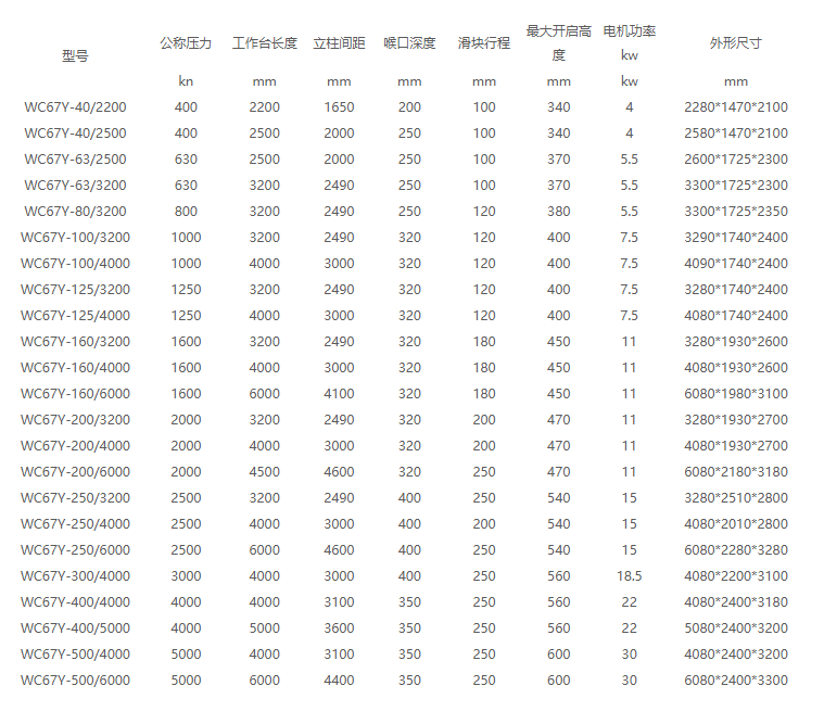
Technical Specifications: