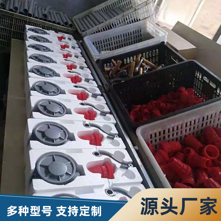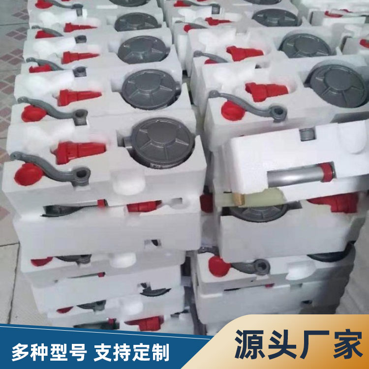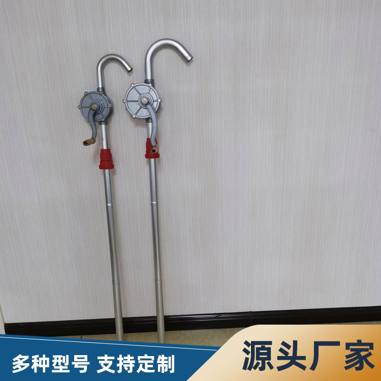


Application Scope:
Automotive steering tubes, brake hoses, A/C hoses, fuel lines, coolant water lines, radiators, heater hoses, hydraulic equipment, condensers, evaporators, air filter hoses, turbocharger system hoses, car brake pumps, cylinder blocks, engineering hydraulic hoses, aviation hoses and manifolds, rigid pipes, fittings, valves, pressure gauges, pressure vessels, pressure transmitters, etc.
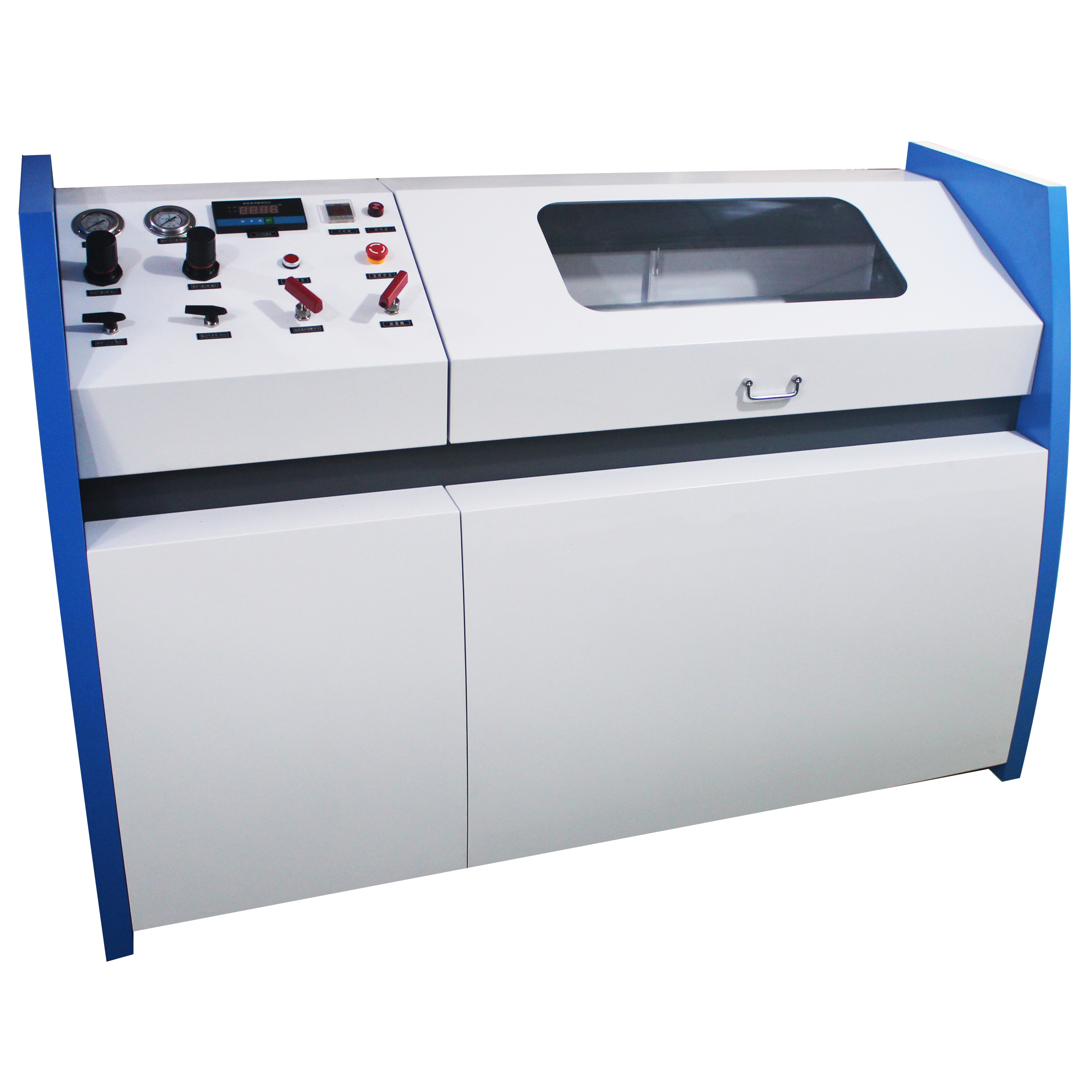
Key Technical Parameters:
Drive Air Source: 0.6-0.8 MPa
Drive gas source flow rate: ≥0.6 m³/min
Burst Pressure: 0-400 Mpa, adjustable as desired
(For a pressure of 400 MPa, the driving gas source pressure must be ≥ 0.8 MPa)
Lift Rate: Proportional solenoid valve adjustable within range.
Measurement Accuracy: ±0.5% F.S.
Pressure Holding Time: Manually set in seconds.
Peak Record: Measurement and Control Labview Software Records
Test Station: 1 Station or Multi-Station
Exhaust System: Semi-Automatic
Test Medium: Pure Liquid Water
Temperature: Room Temperature
Control System: PLC Control
Computers: Lenovo or Rayton mainframes
Touchscreen Monitor
Control Software: LabVIEW Software
Test Report: Microsoft Office
Feature Highlights:
The main components are products manufactured and supplied by our company.
2. The piping system utilizes non-welded connections
3. Control fluid system and separate the drive fluid system for easy observation of test temperature and diverse test medium options.
4. Two different control methods are available for selection: manual control, computer control
5. Utilizing high-speed sampling cards (U.S. NI) for testing data collection (computer controlled)
6. Software is programmed using Force Control configuration software or LABVIEW (computer control) for a variety of accessory tools, catering to different installation methods for test components.
7. During the testing process, pressure compensation can be automatically performed; after time破裂, pressure drops rapidly, the system automatically stops pressurizing, displays the burst pressure, and generates the final table.
8. Specially designed protective workwear that effectively shields operators and equipment from the hazards of explosions.
9. Computer control features include freely adjustable filling and exhaust times, pressure holding times, and water rinsing times. Before the test pressure experiment, single or multi-stage pressure holding tests can be set at will. Pressure holding followed by direct bursting can be set, with adjustable and constant pressure rise speed. The equipment can be infinitely adjusted, and test data and curve parameters are displayed in real-time. The test results can be automatically saved and test reports can be printed at any time after manual termination or bursting. (Computer control)
Process Description:
Add lubricating oil to the oil atomizer of the two-piece unit. In the south, use No. 10 or No. 20 mechanical oil, and in the north during winter, use antifreeze mechanical oil or low-viscosity hydraulic oil.
2. Fill the storage tank with water or other liquids.
Firstly, shut off the drive gas source cut-off valve, connect the gas source, and adjust the pressure reducing valve on the two-piece assembly to ensure the drive pressure is ≤0.8 MPa.
4. When using water as the pressure testing medium, replace the corresponding connector according to the thread size of the test hose fitting, connect the test hose filled with water, close the stop valve, open the water supply valve, open the high-pressure stop valve. Open the drive gas switch. The air-liquid booster pump starts, depending on the different pressure ratios of the pump, when the gas source pressure is set to 0.7 MPa:
Output Liquid Pressure = Drive Gas Pressure * 7
After the test piece is installed, evacuate the internal gas of the test piece, turn on the power switch, manually rotate the drive gas pressure regulating valve to adjust the pressure between 0.4-0.8 Mpa, manually set the output pressure and hold-time, then press the work switch on the operation panel. The equipment will automatically complete the test according to the "steady pressure increase - timing hold-pressure - relieve pressure" process. The high-pressure cut-off valve is a conical valve pin, and the closing force must not exceed 18N/m. If there is a leak in the cut-off valve during the pressure increase process, the correct operation is to relieve pressure and then re-close it. Avoid excessive force to damage the valve core and shorten the valve's service life.
Upon completion of the pressure-holding time, the buzzer sounds, indicating the end of the test, and unloading is required. During the test, automatic pressure compensation is available, offering advantages such as stable test pressure and high pressure testing accuracy. If the specimen fails, the pressure drops rapidly, preventing continuous high-pressure liquid ejection, thereby maximizing safety for personnel and machinery. After the highest pressure on the equipment's pressure gauge is reached and the timer ends, simply copy the pressure curve records to a USB drive.
Safety Precautions and Maintenance for Blasting Test Bench:
When conducting hydraulic tests on containers, it is essential to thoroughly evacuate the air inside the container and its connecting pipes. This is particularly necessary when performing high and ultra-high pressure pressure tests on the container, as it ensures a smooth and safe increase in pressure.
During pressure testing, operators must monitor the pressure gauge's rise and check for any leaks at the connections. If any issues are detected, the pump should be immediately stopped and the pressure released to eliminate the problem.
3. The booster pump serves only to increase pressure; starting it does not increase displacement. Therefore, when filling the inspected container with liquid, the pump should be stopped to prevent unnecessary wear on the booster pump's sealing components.
4. The oil atomizer must contain lubricating oil to lubricate the pneumatic pump. The oil volume should be adjusted to 15-20 drops per minute, and refueling must be done when there is no air pressure in the cup.
5. Regularly drain the accumulated water in the separator filter. Clean the filter cup water frequently, first with mineral oil and then dry the cup with low-pressure air.
6. The testing medium of this machine must be kept clean. It is necessary to regularly clean the water tank and filter screen, as a dirty testing medium can lead to inadequate sealing of the valves on this machine, affecting its operation.
Safety Precautions for Explosive Test Bench Operation:
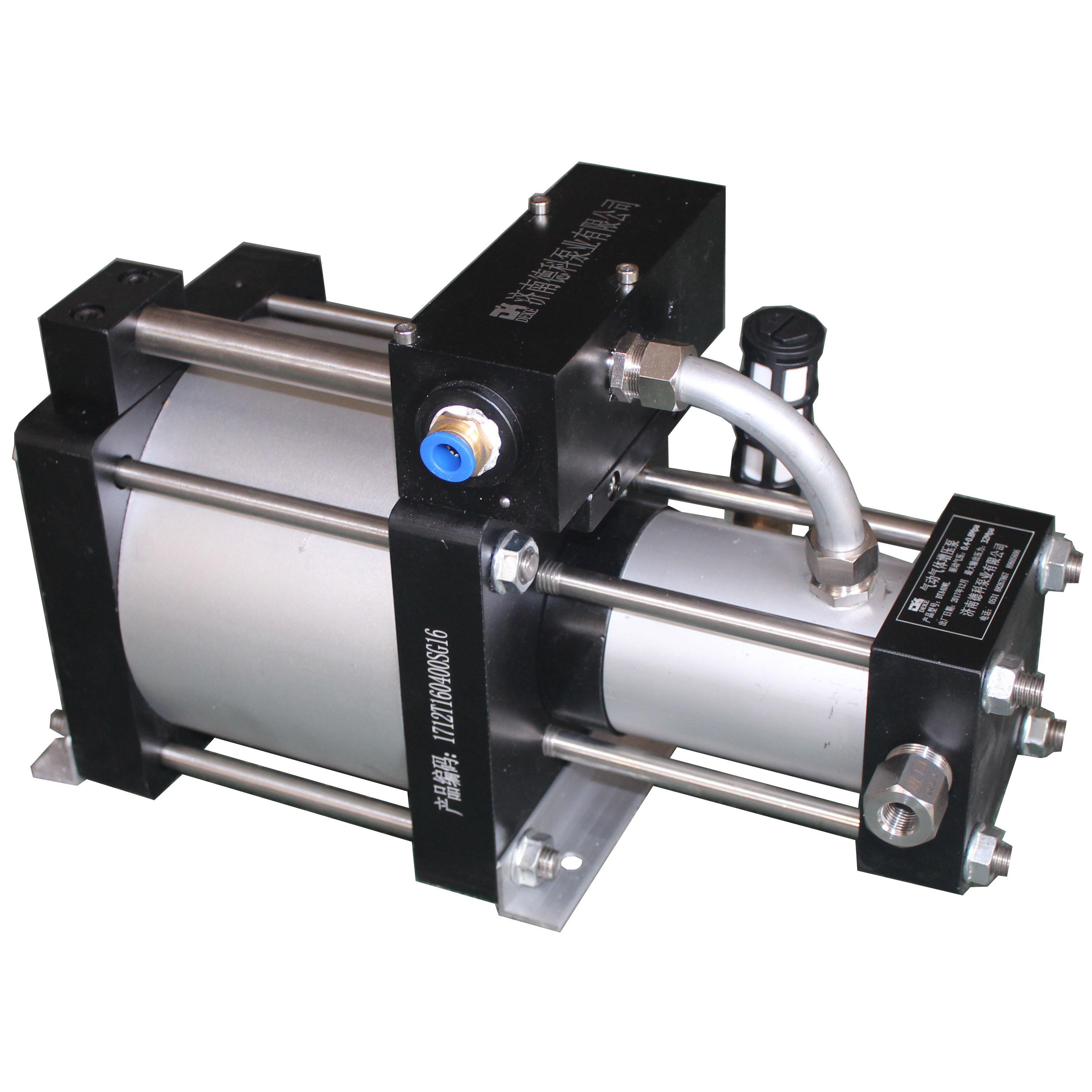
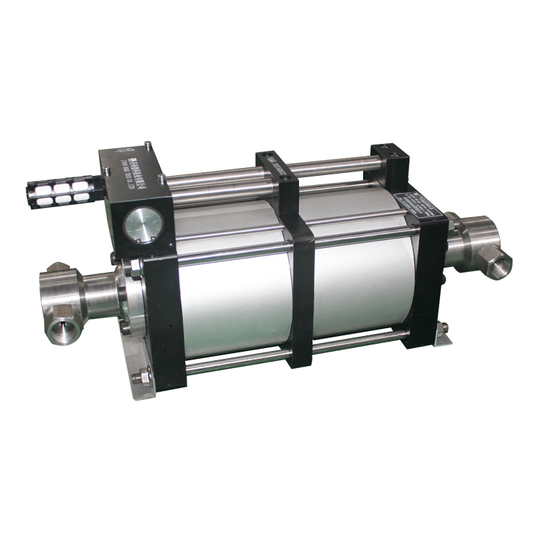
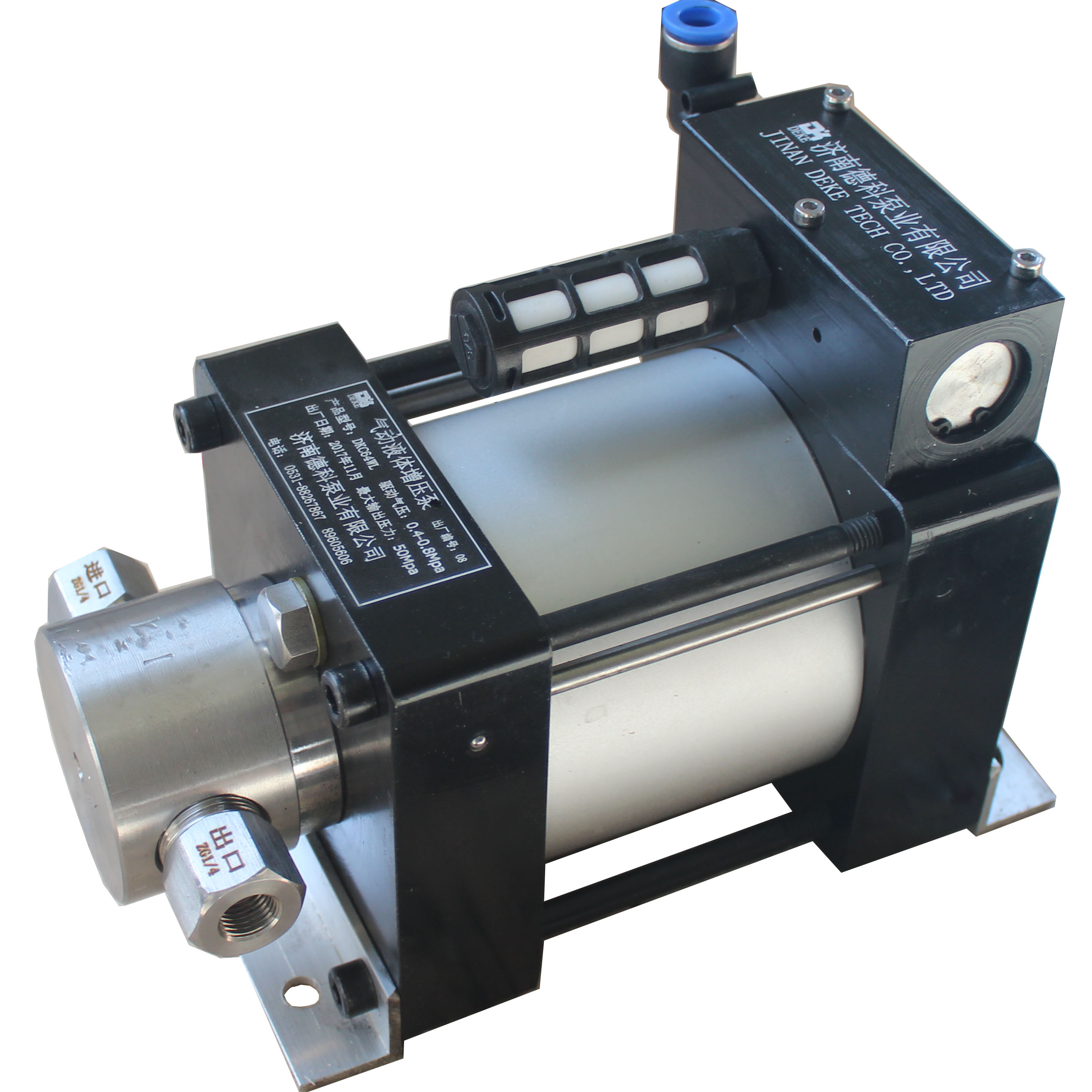
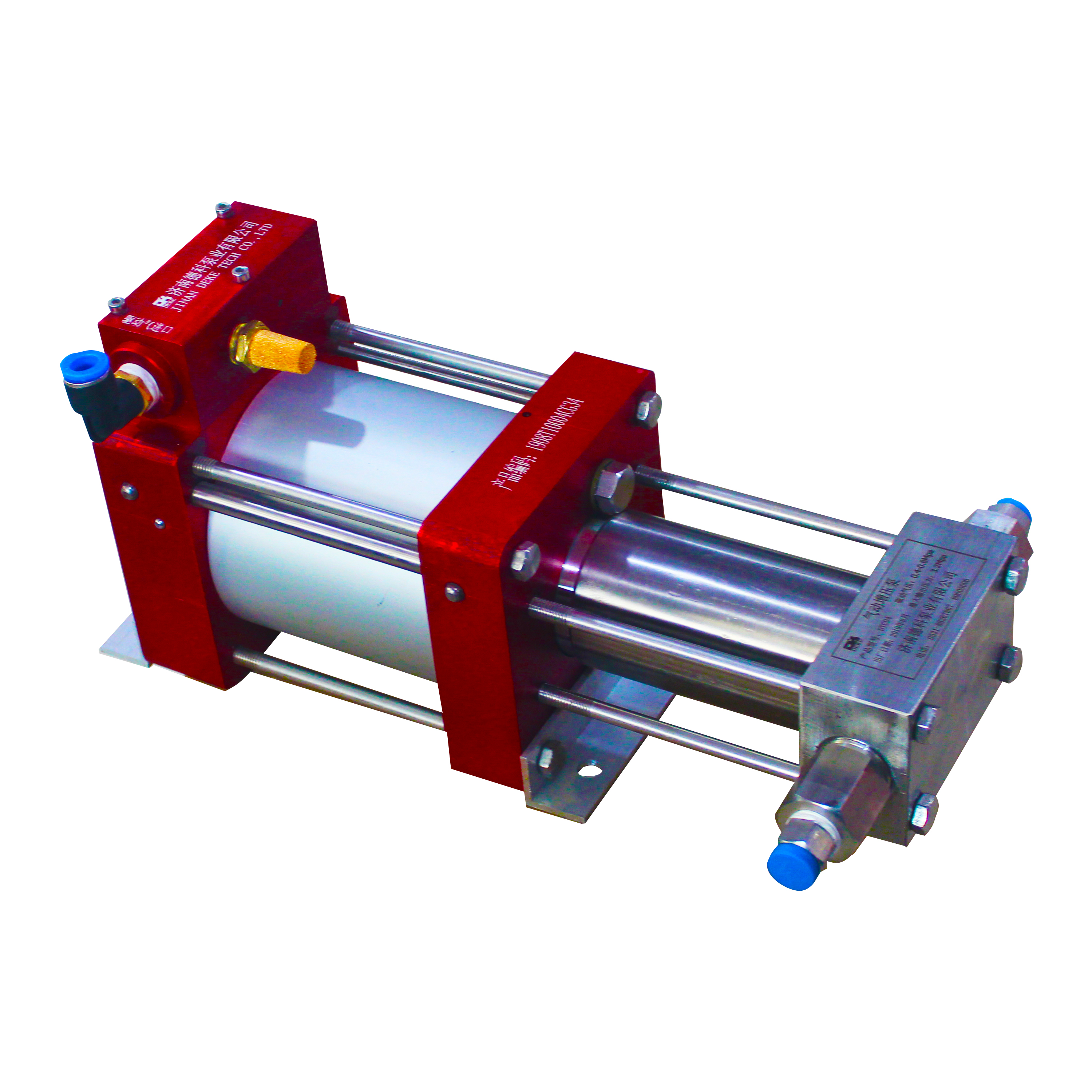
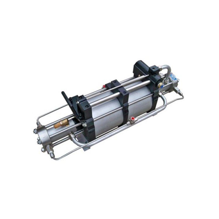
The core component of this equipment is our independently developed gas-liquid booster pump, which boasts high output pressure, easy adjustment, automatic pressure holding, and high cost-performance. Due to these features, it has been widely used. By adjusting the regulating valve, the input pressure can be controlled, and the output gas can be infinitely adjusted accordingly.
Product After-Sales Service:
Jinan Deko Pump Industry Co., Ltd. offers a one-year warranty from the date of product shipment for original defects caused by materials and manufacturing issues. Any failure of parts due to metal materials, seals, improper maintenance, unsuitable liquids used, impurities in air or liquid media, or exceeding the specified pressure are not covered under the warranty. Customers may return products deemed to have original defects to the factory for repair or exchange. Products confirmed by the factory to have defects caused by original issues will be replaced or repaired free of charge. Returns within the warranty period require factory consent prior to shipment. Material returns must include the purchase date, purchase order number, model, reason for return, or other relevant data listed in the warranty application document for timely return of the defective items or replacement parts. Disassembling units without prior authorization, misuse, modification, improper reinstallation, or using non-originary factory-made accessories will also invalidate the warranty.
Any modification to the product, whether already made or to be made, will invalidate the product's warranty. For products that have been modified, Jinan Deko assumes no responsibility or obligation. Jinan Deko Pump Co., Ltd. will not accept any claims or demands for personal injury resulting from the modification or use of modified Jinan Deko products.
The obligations of the product are limited to replacement only. Jinan Deko Pump Industry assumes no responsibility for any losses due to natural causes, human error, or contamination, nor does it cover expenses incurred from installation requirements or during usage.