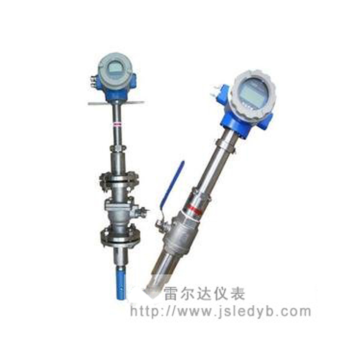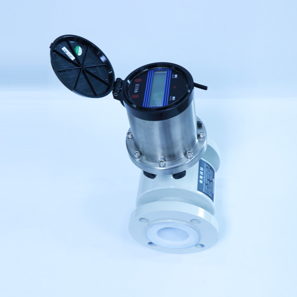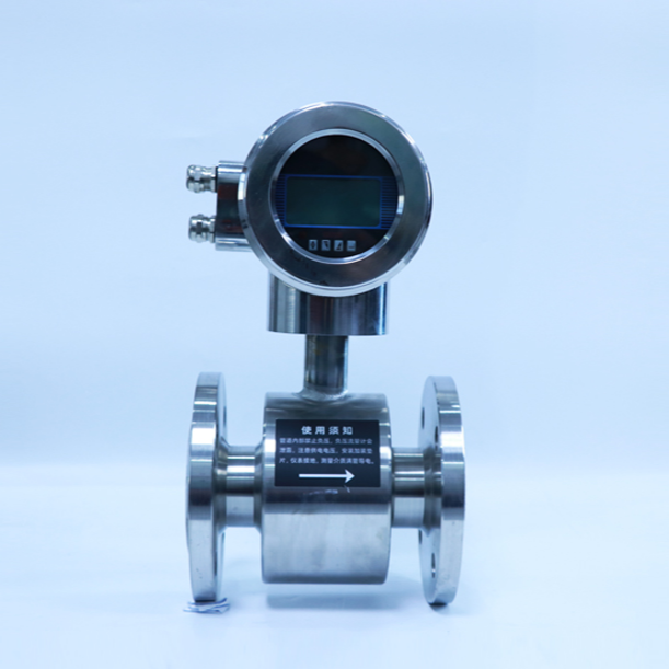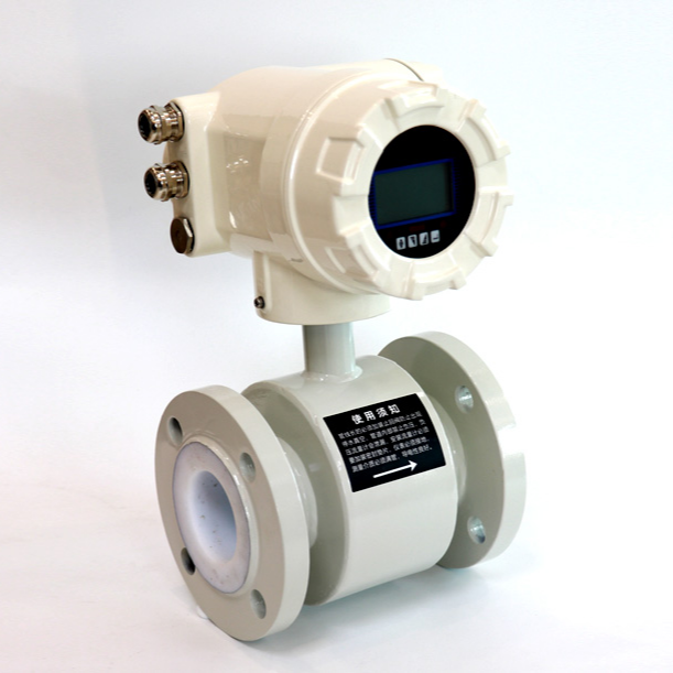
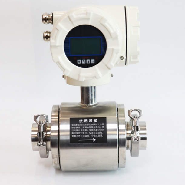
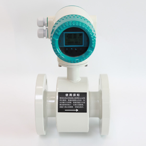


LRD-LGDType Insertable Electromagnetic Flow Meter Overview LRD-LGDType Insertion Electromagnetic Flow MeterLRD-LGDThe type insertion electromagnetic flow sensor (hereinafter referred to as the sensor) is paired with an electromagnetic flow converter. The insertion electromagnetic flowmeter is available in two types: with and without a shut-off valve. It is suitable for large and medium-sized pipelines in industries such as potable water, petrochemicals, and has the capability to measure the instantaneous and volumetric flow of conductive liquids. It is particularly suitable for flow measurement in industries such as metallurgy, papermaking, and wastewater treatment.
2. Insertion electromagnetic flowmeter - Features
Insertable electromagnetic flow meters, in addition to the general characteristics of electromagnetic flow meters, also have their own unique advantages:
1. Simple structure, no moving parts, and long service life.
2. Compact, lightweight, easy to install, and low maintenance.
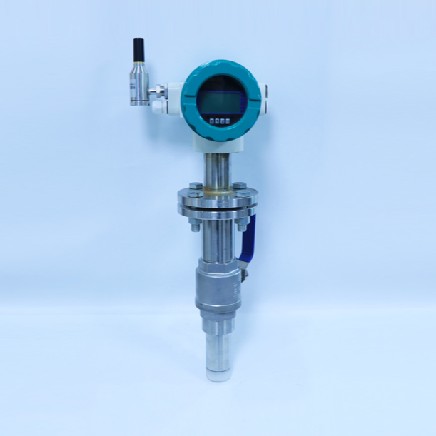
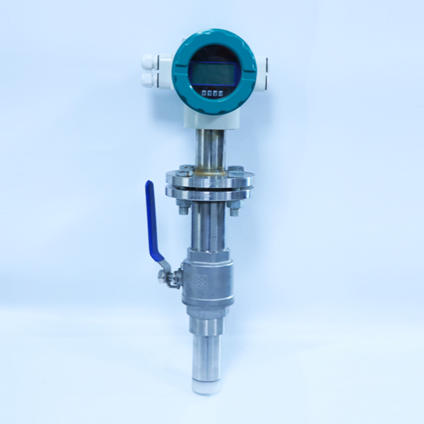
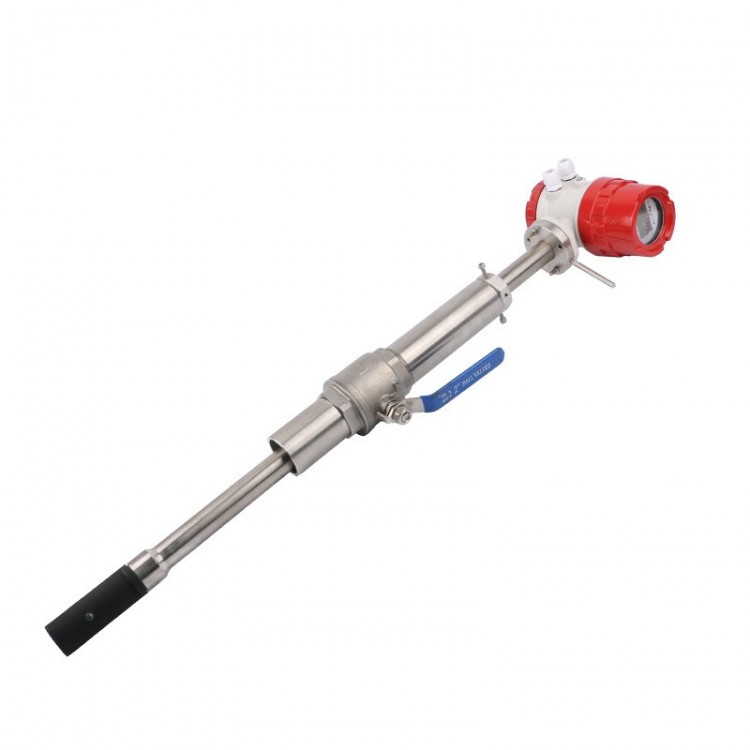
3. The plug-in electromagnetic flow meter with a shut-off valve allows for installation and removal without the need to shut off the flow, making maintenance and repair convenient for users.
4. Measurement is unaffected by the material of the pipe being tested.
5. No lining required, no grounding ring needed.
【Product Features】
1. Unaffected by variations in temperature, pressure, density, viscosity, and electrical conductivity (not less than the minimum conductivity).
2. The sensor has a simple structure, without throttling components, and is not prone to clogging, making it suitable for environments with solid particles, fibers, and suspended matter such as...
Measurement of slurries, paper pulp, mineral pulp, wastewater, etc.
3. Easy installation without interruption of flow; on-site piercing is possible under pressure (below 1.0 MPa), both economical and convenient.
4. Display cumulative flow (14 digits), instantaneous flow (6 digits).
5. Easy operation settings are available via magnetic isolation keys, the panel's keyboard, a hand-held operator, or a supervisory computer.
6. Zero-point self-calibration, eliminating zero drift.
7. The range can be set arbitrarily within the calibrated maximum flow range.
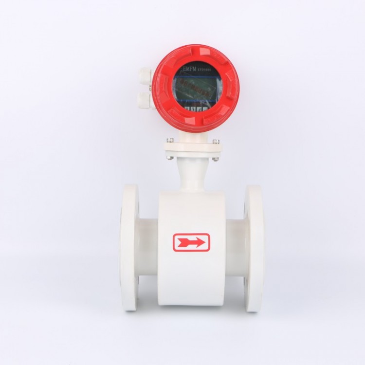
8. Bidirectional flow measurement; standard factory setting is positive flow direction unless otherwise specified.
9. Mini-signal cutoff feature, allowing users to set the cutoff of interfering low flow via the display panel.
10. Upper and lower limit alarms; users can set the upper and lower limit of instantaneous flow according to actual needs. When the flow exceeds the upper limit or is lower than
The buzzer will alarm or the relay will output (user selectable) when the lower limit set value is reached.
11. Airflow Gauge Judgment: In the operating state, when the airflow gauge measures air in the pipeline, the instantaneous flow display shows EPo.
12. Password lock function: After the flowmeter is powered on, if parameter settings are required, a four-digit password must be entered to proceed with parameter setup.
13. Power failure protection feature ensures that the flow meter's calculation results and user-set parameters are not lost after a power outage, stored in E2PROM.
Storage, data can be preserved for a long term, and the current hourly cumulative traffic within the last 24 hours can be checked via the panel operation.
14. Sliding Filter 0-20
15. The仪表Coefficient can be corrected for different conductive mediums.
Section 3: Insertion Type Electromagnetic Flowmeter Technical Parameters
1. Applicable Pipe Diameter: ≥200mm
2. Sensor Material: Stainless Steel (1Cr18Ni9Ti)
3. Flow Measurement Range: 0.1~10 m/s
Range: 0.5~10 m/s
Recommended for use in wind speeds of 1~5 m/s.
4. Conductivity of the tested liquid: > 5 μS/cm
5. Working Pressure: 1.0 MPa, 1.6 MPa, 4 MPa, 25 MPa
6. Test Medium Temperature: -40℃ to 0℃, 0℃ to 70℃, 70℃ to 180℃
7. The allowable angle deviation between the sensor locating rod axis and the pipeline axis is +5°, and the allowable insertion depth deviation is 3mm.
8. Straight Pipe Length Requirement: Straight pipe section length upstream of the sensor ≥ 20D; straight pipe section length downstream of the sensor ≥ 7D
9. Main Technical Performance Indicators of the Converter:
Output Signal: 4~20mADC, Load ≤ 750Ω
0~3 kHz, 5V active, variable pulse width, high-efficiency frequency output.
RS485 Interface
b. Power Supply: 220VAC ±10%; 50Hz ±1Hz; 24VDC ±10%
c. Power Consumption: ≤8W
d. The maximum length of the connecting cable between the sensor and transducer is 100 meters.
e. Working Environment: Temperature 0~40℃; Relative humidity less than 85%; No corrosive gases should be present in the surrounding air.
f. Show instantaneous flow and cumulative flow
8. Accuracy: ± 1.5%R when the nominal diameter DN of the pipeline is ≤ 150
When the nominal diameter of the pipe (DN) is ≥ 200, the tolerance is ± 1.5%R ± 2.5%R.
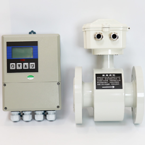
10. Enclosure Protection Class: Integrated: IP65; Modular: Sensor IP68; Converter IP65
Section 4: Selection Parameters and Model Markings
For insertion electromagnetic flow meters, the design unit should select the model based on the main technical specifications of this product and refer to the actual conditions of the user.
1Determination of Applicable Traffic Range
If the user has already installed the pipeline, they can select the appropriate flow rate and sensor diameter from the table.
If the user has not prepared the pipeline, the first step is to determine the sensor diameter based on the flow range, and then consider whether to install a sensor with a shut-off valve or without one.
2Probe and insertion rod styles
The probe type is determined based on the medium's suspended particle condition. Generally, for more suspended particles that are not frequently disassembled, an open type is chosen; otherwise, a conduit type is selected. The rod type is related to installation requirements. The screw rod type is generally easier to install.
3Pressure and usage conditions
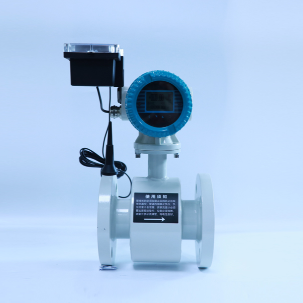
Users can select the pressure specification of the sensor based on the required pipeline pressure. Generally, insert-type electromagnetic sensors are used in scenarios with lower pipeline pressure and are suitable for measuring circulating water, source water, and pure water in large and medium-sized pipelines. Additionally, the insert-type electromagnetic flow meter is more cost-effective compared to integral or split electromagnetic flow meters with the same diameter.
Five、LRD-LGD Type Sensor Selection Chart
LRD-LGDInsertable Electromagnetic Flow Sensor
Installation Method - (With shut-off valve; 1 - Without shut-off valve)
Probe Type - (A: Open Type, B: Tube Type)
Rod Type – (1 Screwed Rod, 2 Smooth Rod)
Bore Size – (see Table 1)
Section 6: LRD-LGD Insertion Type Electromagnetic Flow Meter Selection Chart
LRD-LGDInsertable Electromagnetic Flow Meter
Application Environment - (B: Explosion-proof; No: Non-explosion-proof)
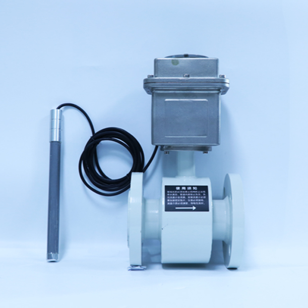
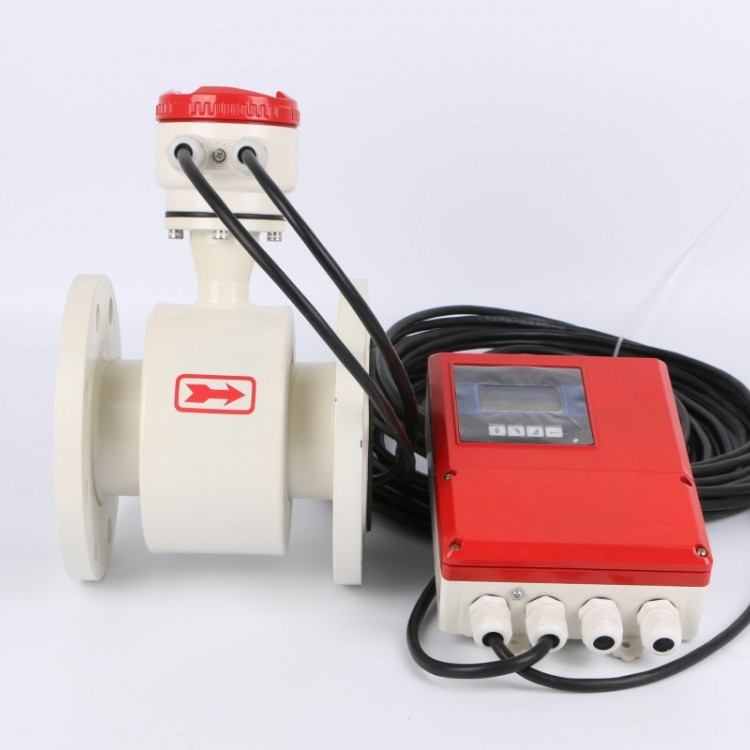
Converter Model - (6A: Integrated; 5A: Split Type)
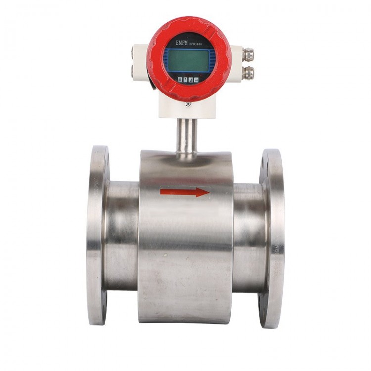
Structure Type - (Y: Integrated: Split Type)
Installation Type —— (With Shut-off Valve; 1 - Without Shut-off Valve)
Probe Type - (A: Open Type; B: Tubular Type)
Retractable Rod Style - (1 Screwed Rod; 2 Smooth Rod)