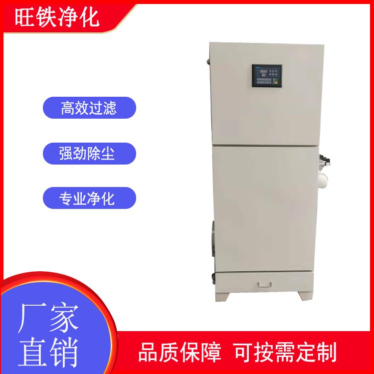


Working Principle
Upon entering the dust collector's hopper, the dust-laden gas, due to the sudden expansion of the airflow cross-section and the action of the distribution plate, causes some coarse particles to settle at the bottom of the hopper under the influence of dynamic and inertial forces. Fine particles with low density enter the dust-filtering chamber and, through a combination of Brownian diffusion and sieve filtration, deposit on the filter material surface. The purified gas then enters the clean air chamber and is exhausted through the exhaust pipe via a fan. The resistance of the filter tube dust collector increases with the thickness of the dust layer on the filter material surface. Cleaning is performed when the resistance reaches a specified value.
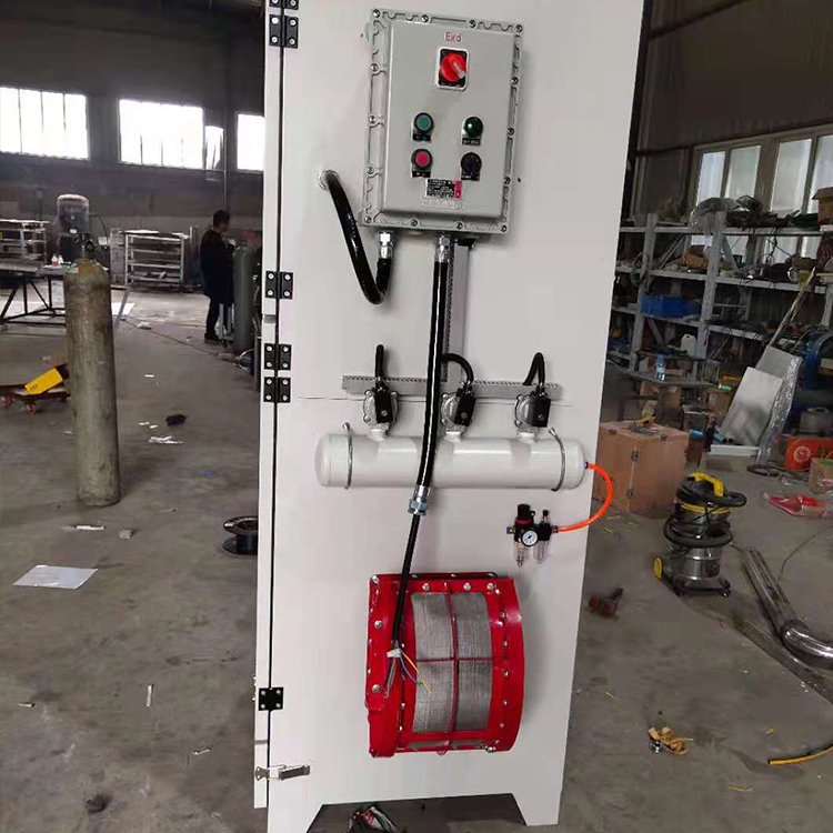
At this point, the PLC program controls the opening and closing of the solenoid pilot valve. Firstly, the isolation valve of the first chamber is closed to cutoff the filtered air flow. Then, the solenoid pilot valve is activated, causing compressed air and a brief period of rapid expansion within the upper chamber, which floods into the filter housing. This causes the housing to expand and deform, generating vibration. Under the action of the reverse airflow, the dust particles adhered to the outer surface of the filter bag are peeled off and fall into the ash hopper. After cleaning, the solenoid pilot valve is closed and the isolation valve is opened, restoring the filtering state of the chamber. The cleaning process is carried out sequentially in each chamber, from the first cleaning to the start of the next cleaning, constituting a cleaning cycle. The fallen dust is discharged into the ash hopper through the ash discharge valve.