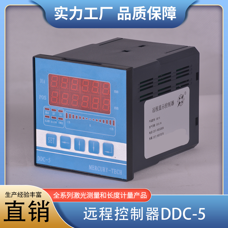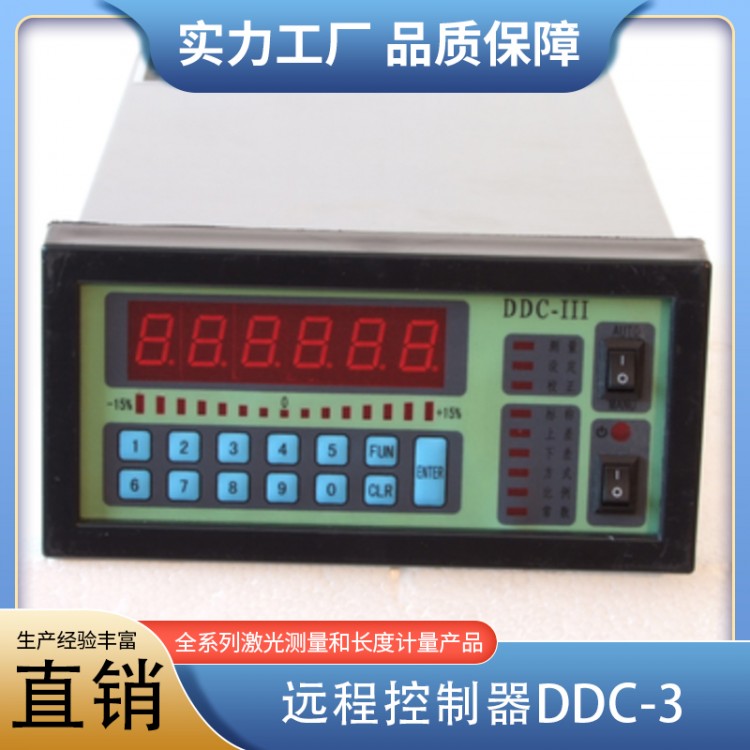

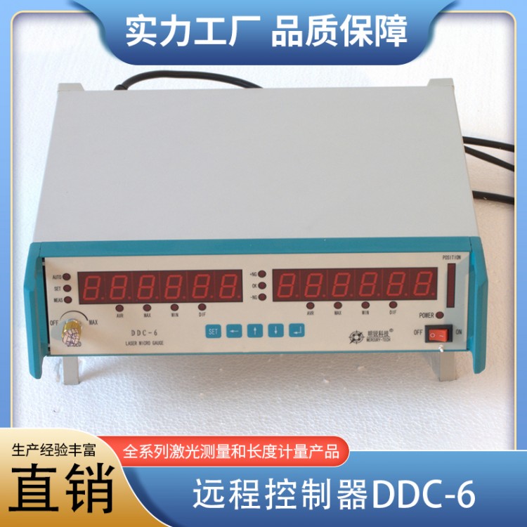


Product Name: Remote ControllerDDC-3
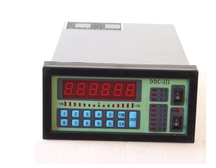
Dimensions:164mm*84mm*280mm
Hole size:152mm*76mm
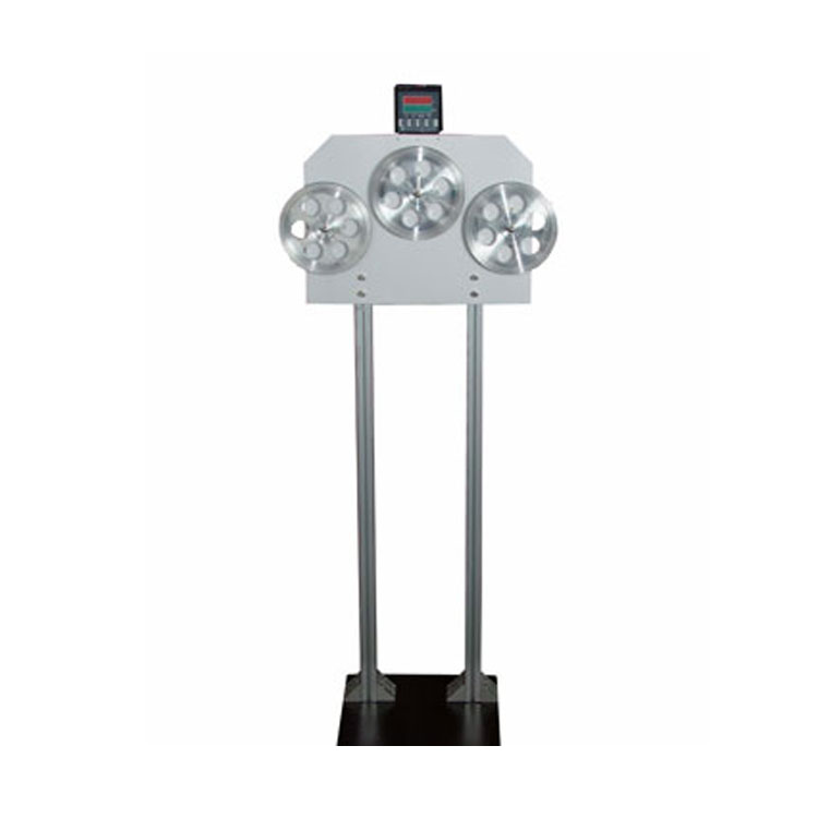
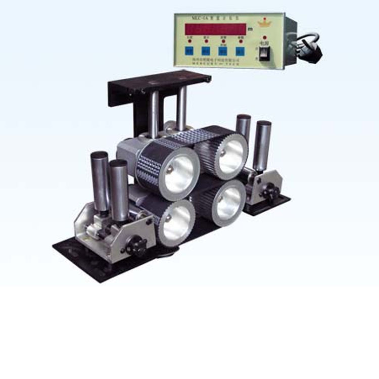
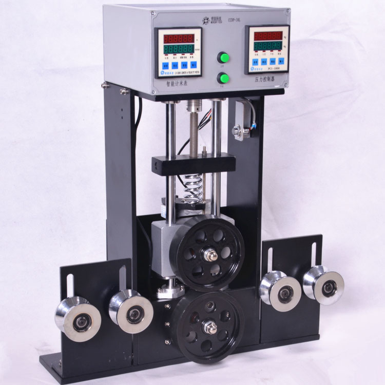
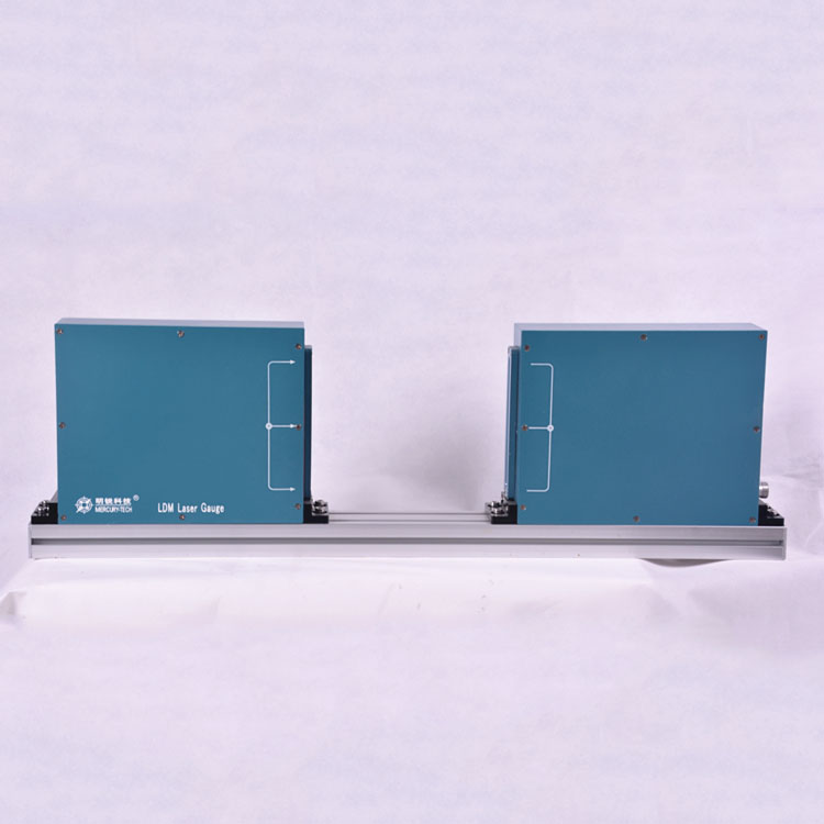
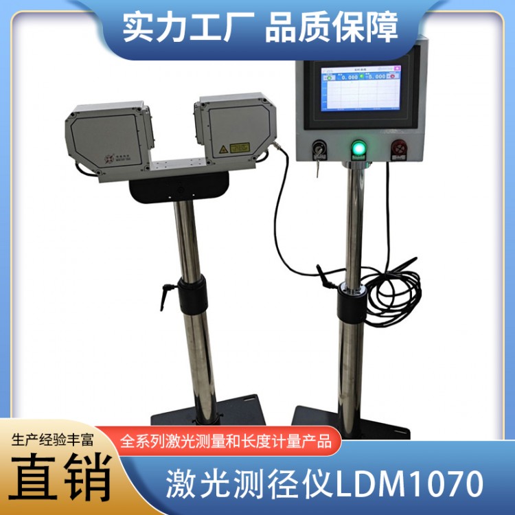
LDMSeries External Diameter Measurement and Control Device
One Overview
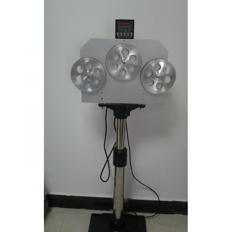
LDMSeries outer diameter measuring and controlling devices are high-precision measuring and controlling devices that use light and electricity for non-contact online measurement. They are mainly applied in production lines of various wires, cables, and pipes, measuring the outer diameter of the measured objects. They also output error signals, adjusting the screw speed of the extruder or the speed of the puller, to achieve the purpose of measuring and controlling the outer diameter.
Outer Diameter Measurement and Control Device - Model Applicability Range:
CDM--□□ Standard Type: Used for measurement and control of rubber, plastic extrusion lines, bare wires, magnetic wires, etc.
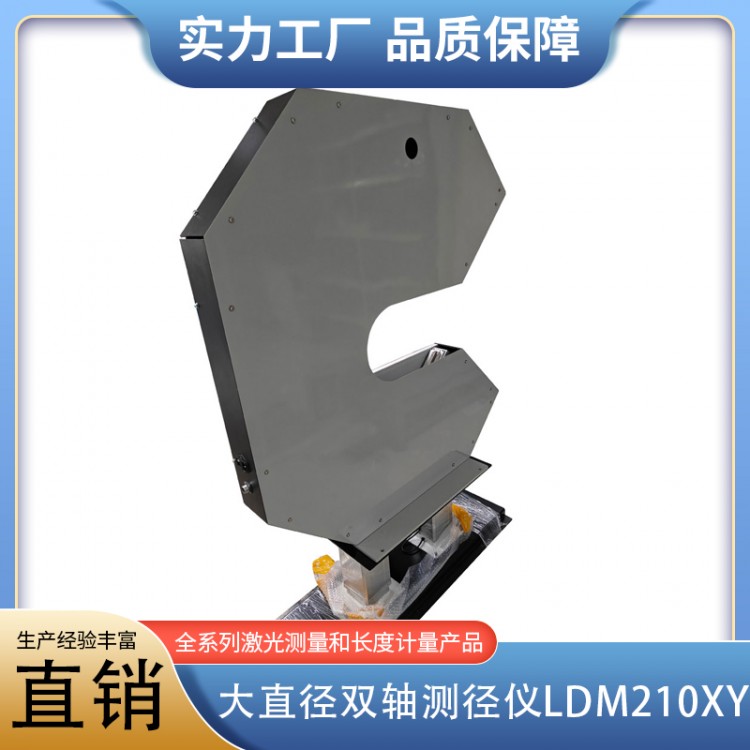
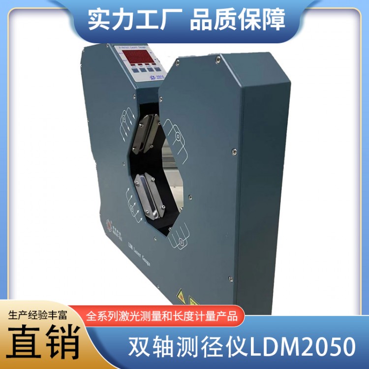
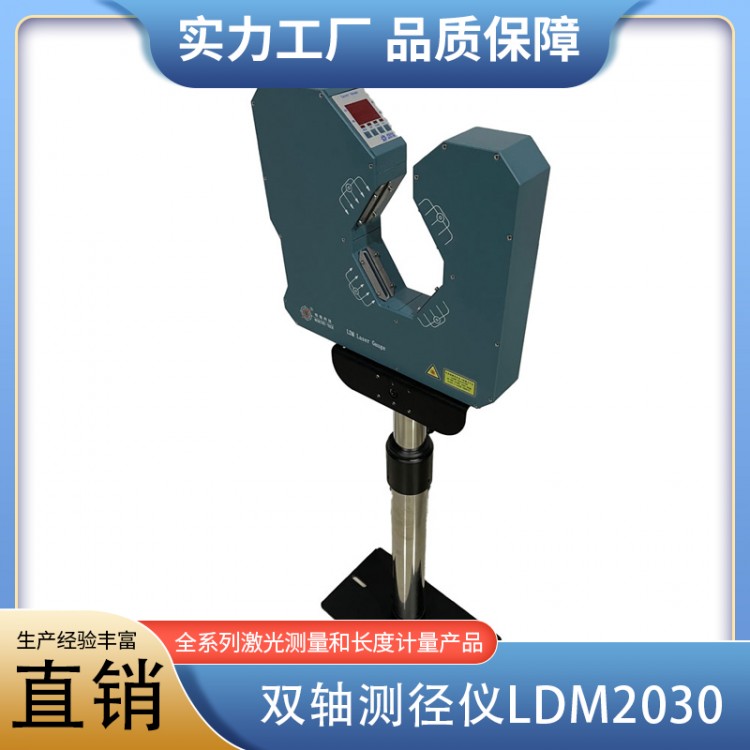
LDM--□□□Laser Type: For applications requiring high precision.
CDM--□□□FType: Used for measurement and control of continuous vulcanization, three-layer extrusion, crosslinking lines, and large-diameter wires, cables, and pipes.
CDM--□□TType: For measurement and control of transparent or semi-transparent cables, optical fibers, and conduits.
DDC-IIDisplay Control Unit: For remote display and control of signal output, desktop enclosure.
DDC-III-□□□ Display Control Unit: For remote display and control of signal output, cabinet-style enclosure.
Suffixes indicate different signal output forms:
DDC-III-ESVoltage Series TypePIAdjust output, output voltage = set signal ±30%, suitable for DC speed controllers or variable frequency speed controllers, etc.
DDC-III-EPVoltage Parallel TypePIAdjust output, output voltage range = -2.5~2.5V, Impedance=470Ω, suitable for speed controllers for electromagnetic variable-speed motors, etc.
DDC-III-PProportional voltage output; the output voltage is directly proportional to the outer diameter.0-10VApplicable toPLCAnd industrial control computers.
Operating Principle
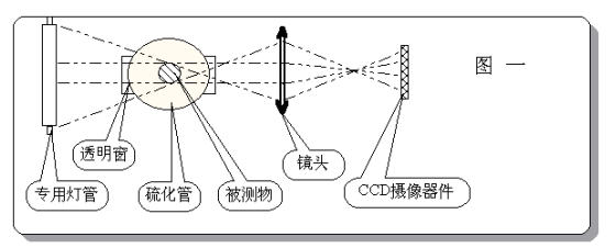
CDMThe measurement head of the series of outer diameter control devices is composed of two major parts: optical path and circuit.CDM--□□□FThe model is illuminated by tube lights, with the lens forming the image.(See Figure 1)。
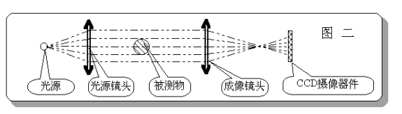
CDM--□□、CDM--□□THigh-brightness infrared measurement headLEDParallel light illumination to the optical lens, imaging by the lens(See Figure 2)。
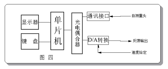
CDMThe circuit parts of the series external diameter measuring and controlling devices are basically the same (see Figure 3), justCDM-□□□FThe model displays data through the display control unit. Other models show data on the measurement head, and can also be equipped with a display control unit to form a dual-display structure. The principle of the display control unit is shown in Figure 4.
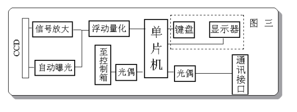
Tested wires, cables, and pipes are projected onto an image sensor after being magnified or reduced by an imaging lens.(CCD)Up.CCD数千 evenly spaced photo-sensitive units on top, outputting signals when an image is present. Illuminated photo-sensitive units have stronger signals, while those obscured by the image have weaker signals. The microprocessor samples and analyzes the signals to obtain the image size.
CDMThe series of outer diameter measuring devices utilize high-speed sampling technology to overcome the influence of up and down vibrations in wires, cables, and pipes. The optical design effectively combats the effect of minor left and right vibrations within a small range, fully meeting the online measurement requirements for wires, cables, and pipes.
Due to its digital measurement principle, coupled with a precise optical system, microprocessor, and more, this device boasts high precision, stability, and reliability. Sex, etc.
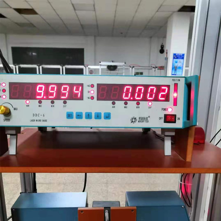
Monitor: Six-digit upper leftLEDDigital display for displaying measured values and set parameters.
(2) Control Volume Indicator: Located in the lower left corner, it indicates the adjustment range of the set speed quantity for the controlled device by this machine.
(3)Control Switch: Automatic on the upper right of the panel/Manual control switch. The switch is set to:AUTOLocation, operating in automatic adjustment mode; switch set toMANULocation, operates in manual adjustment mode.
(4) Status Indicator Lights: Nine status indicator lights are located in the center of the panel, indicating the working status.
① "Measure" indicator light: Indicates operation in measurement mode, displaying the outer diameter value.
② "Set" Indicator: Indicates that the machine is operating in the parameter setting state.
③ "Calibration" Indicator: Indicates that calibration is in progress. At this time, data can be modified to make the displayed value equal to the outer diameter of the standard rod.
④ "Nominal" Indicator: Lights up simultaneously with the "Set" Indicator to indicate that the unit is in nominal value setting mode, displaying the nominal value.(The wire diameter you need)
⑤ "Upper Deviation": Illumination indicates that the measured outer diameter exceeds the upper deviation. During setup, it indicates that the machine is in the "Upper Deviation" setup state, with the displayed value being the upper deviation value.
⑥ "Under-size": Illumination indicates that the measured object's outer diameter exceeds the under-size. During setup, it indicates that the machine is in "Under-size" setup mode, and the displayed value is the under-size deviation.
⑦ "Mode": Indicates that the machine is in the control mode setting state.
⑧ "Ratio": Indicates the status of the machine's ratio coefficient setting, factory default value20。
⑨ "Constant": Indicates that the machine isPIDControl parameter setting status.
Please provide the Chinese content that needs to be translated into American English."Constant" setting state has3UnitPIDParameters, displayed:
“P XXX.X” EstablishPIDProportional coefficients with factory set values30;
“I XXX.X”EstablishPIDPoints with coefficient, factory set value15;
“d XXX.X”EstablishPIDThe differential belt coefficient, factory set value2.5。
(5) Button: Located on the right side of the panel
“ENTER"Key: The confirm key. Pressing this key ends the setup of a parameter data."FUNPressing the keys simultaneously will allow the device to enter the calibration state from the measurement state.
“CLR"Key: The Clear key, used to erase a digit entered after it."FUNPressing the keys simultaneously allows the machine to enter the parameter setting state from the measurement state.
"0-9": Numeric keys.
(6) Power switch and power indicator light: Located at the lower right corner of the panel.
2Calibration
The display control unit is factory-calibrated for accuracy and generally does not require adjustment. However, if the measurement head is mounted in front of the cooling water tank, due to the heat from wires, cables, and piping. The state value is greater than the cooled value, hence the hot state value needs to be multiplied by a coefficient for display.
Calibration Process: Place a standard rod or wire, cable, or tubing with a known outer diameter on the guide wheel, and the instrument operates in"Measurement" state, after the instrument has stabilized, press first theFUN"Keep the key pressed, then press "ENTER Press and release two keys, at which point the "Calibrate" indicator light illuminates. Enter the standard outside diameter using the numeric keys, then pressENTER"Key, countdown to zero displayed, calibration complete."
This calibration method is only effective for the display control unit.
3. Parameter Settings
For each specification of wire, cable, and pipe, implement feedback control and set the control parameters as follows:
Please provide the Chinese content to be translated.In "Measurement" mode, pressFUN"Press and hold the key while pressing"CLR"Key, at this point the 'Set' and 'Nominal' indicator lights illuminate, and the display shows the previously set nominal value. Enter the new nominal value using the numeric keys, and press "ENTER"End the setting of the nominal value. At this point, the 'Up Error' indicator light illuminates, allowing you to set the upper deviation. Continue until all six parameters are set, then the machine returns to the measurement state."
4. Measurement
The machine operates normally, entering immediately upon startup."Measurement" state, at which time the "Measurement" indicator light is on.,The displayed value is the outer diameter.
As measured value>Nominal Outer Diameter+When there is an upper deviation, the "upper deviation" indicator light illuminates; whereas the measured value<Nominal Outer Diameter-When there is an under deviation, the "under deviation" indicator light illuminates. In case of exceeding the deviation, an alarm signal is output by the interface circuit, which can trigger an alarm from the alarm device.
If the startup screen displays “ Err1"Indicates that the correction data or set parameters of this machine are lost. Please recalibrate and reset all parameters."
Six. Feedback Control
1. Wiring:
To implement feedback control, it is necessary to properly connect the control lines according to the method described in Section 3.
2. Selection of Control Parameters
Named, Upper Deviation, Lower Deviation: Set according to manufacturing process standards.
Method: Select for1Or2。
Method1Positive error ─ output voltage increases. Suitable for controlling the traction speed of cable production equipment.
Method2Positive Error ─ Decreased output voltage. Suitable for controlling the extruder screw speed of cable production equipment.
Ratio: ForPIDAdjust output; the ratio is the percentage of speed change corresponding to 1mm compensation error; for error ratio output, the ratio is1mmThe output voltage resulting from error is compared with the full-scale voltage (usually the full-scale voltage is set at the factory).5VThe ratio of ). For example, when the error is 1mm, the output voltage is2VNo Chinese content provided.:
2V
Ratio =----×10040.000
5V
Constant:P、I、DParameters are generally taken from the factory's set values. When the line speed is fast, it can be appropriately increased.PAndIParameters.
3. Test Run
Power on and start the vehicle simultaneouslyDDC-IIIPower switch, at this point the control is manual.(MANU)Method. First, stabilize the production line and adjust the wire diameter to the nominal value. Then press the control button; the indicator light on the button will illuminate, indicating that it is in automatic mode.(AUTO)Monitor the output indicator and the change in wire diameter. If the wire diameter gradually approaches the nominal outer diameter with the change in control output and without significant oscillation, the adjustment is complete. If the wire diameter gradually deviates from the nominal value, it indicates incorrect control polarity; change the control method.(Originally1Revised2, previously known as2 Revised1)If the adjustment speed is too slow, you can appropriately increase the "proportion" parameter or the constant in the "IParameters. If adjusting the speed too quickly causes oscillation, reduce the "proportion" parameter or constant.IParameters.
4. Utilize
At power-on, the controls should be set to:“MAUN"Method: Once the manufacturing equipment operates stably and the cable outer diameter is close to the nominal value, press the control button to enter"AUTOMethod.
Chapter 7: Communication Interface
1 ThroughDDC-IIIDisplay Control UnitRS485Interface, enabling communication between the device and computers, etc.DDC-IIIFor one-way communication, meaning data is sent out only, with a cycle of2Frame/Milliseconds, per frame of data9Bytes, per byte11Positions, including1A starting position.8A data bit.1A parity bit1A stop bit. The baud rate for serial transmission is:2400bps。DDC-IIIAdoptedASCIIThe data is represented in a binary format. The definition of each digit is as follows:
B1、B2 、B3 、B4、B5、B6: DataASCIICode
B7、B8: Verification CodeASCII)
B9: End CodeCR)
When the measurement result is123.456mmAt present, communication data is
B1 B2 B3 B4 B5 B6 B7 B8 B9
No Chinese content provided.“1” “2” “3” “4” “5” “6” “0” “2” CR(0x0D)
HEX: 31 32 33 34 35 36 30 32 0D
(DescriptionB7B8Please provide the Chinese content to be translated.12+34+56The sum102The low2Value of the bit.)
2Computer Display Software
Real-time outer diameter display, shift records, real-time outer diameter curve, alarm.
Section 8: Common Fault Handling
Fault1The measurement head or display control unit's monitor is not displaying, and all indicator lights are unlit.
Please provide the Chinese content to be translated. Understanding Inspect the power socket, power switch, and fuse. If all are fine, it's a power circuit issue. Please contact the manufacturer. Manufacturer contact.