


Water Cannon Online Promotion Article
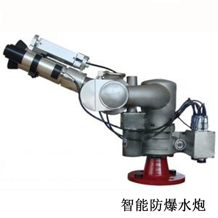
The Automatic Tracking and Locating Jet Fire Extinguishing Device is a high-tech fire protection product developed based on the technological innovation alliance of the second-generation fire cannon technology, integrating automatic alarm, fire tracking, automatic extinguishing, and video monitoring into one.
2. The automatic tracking and positioning jet fire extinguishing device leads with patented infrared thermal imaging positioning technology. In addition to the industry-standard first-generation active red and ultraviolet single-point narrow-slot technology for detecting fire sources, it features automatic positioning, targeted water jetting at the fire point for extinguishing, automatic valve closure post-extinguishing, and restart in case of reignition. Furthermore, it boasts real-time dynamic tracking for changing fire sources, ensuring more accurate positioning.
3. The automatic tracking and positioning jet fire suppression system, in addition to being suitable for general fire monitor applications, can also be used in places where UV lights, welding, and cutting are present outdoors, or in environments where traditional fire hoses are not suitable. It is also ideal for areas that demand high precision in location and system reliability, requiring around-the-clock, fully automated operation.
4. The automatic tracking and positioning jet fire extinguishing device is easy to install, with simple water and power supply, low maintenance costs, water-saving, and significantly reduces the risk of flood after extinguishing. It offers high cost-performance ratio and is widely used in high and large spaces such as cinemas, warehouses, factories, stadiums, grand halls, waiting halls, exhibition centers, hotels, and parking lots.
5. Automatic tracking and positioning jet fire suppression systems are not suitable for operations that normally use open flame production.
6. Automatic tracking and positioning jet fire extinguishing devices are not suitable for Class B, C, or D fires.
7. Automatic tracking and positioning jet fire suppression systems are not suitable for areas with a high concentration of items that burn faster when wet.
8. Automatic tracking and positioning jet fire suppression systems are not suitable for areas where water contact can cause explosions.
9. Automatic tracking and positioning jet fire suppression systems are not suitable for areas where there are numerous items that undergo剧烈 chemical reactions upon contact with water or produce toxic substances.
10. Automatic tracking and positioning jet fire suppression systems are not suitable for locations where liquid may splash or boil over due to sprinkling.
11. Automatic tracking and positioning jet fire extinguishing devices are not suitable for locations housing valuable items that would sustain severe damage upon contact with water, such as archives, valuable documents storage, and museum珍品rooms.
12. Automatic tracking and positioning jet fire suppression systems are not suitable for locations where significant property damage is caused by the impact of high-altitude water cannons.
13. Automatic tracking and positioning jet fire suppression systems are not suitable for other locations where large-space active water sprinkler fire suppression systems are not advisable.
14. The Automatic Tracking and Locating Jet Fire Extinguishing Device is an integrated automated fire extinguishing system that combines computer technology, red and ultraviolet sensing technology, infrared thermal imaging technology, mechanical transmission technology, and image transmission technology. It actively detects the monitored area around the clock in an all-weather, fully automatic manner.
15. The automatic tracking and positioning jet fire suppression system, upon detecting a fire, promptly activates and simultaneously emits an alarm signal. It then engages the solenoid valve and pump to spray water at the fire source for extinguishing. Once the fire is extinguished, it automatically stops. In case of re-ignition, it restarts.
16. The automatic tracking and positioning jet fire extinguishing device can be connected to the automatic fire alarm system and can also be integrated with on-site operation panels, fire monitor controllers, etc., to form a centralized fire extinguishing system.
17. The automatic tracking and positioning jet fire extinguishing device is easy to install, with simple water and power supply, low maintenance costs, and water conservation. It significantly reduces the risk of water damage following fire extinguishing.
18. The automatic tracking and positioning jet fire extinguishing device employs the technical principle of missile guidance tracking. Its core components utilize infrared thermal imaging sensors and array scanning positioning principles. In addition to general civil applications, it is also suitable for complex industrial warehouse environments, certain outdoor settings, or locations with high reliability requirements for the system.
19. The Automatic Tracking and Positioning Jet Fire Extinguishing Device abandons the narrow-slot technology and adopts the same principle as the real-time tracking of the tail flame heat imaging guidance of air-to-air missiles. The core technology utilizes a non-cooled focal plane array thermal imaging sensor with real-time temperature measurement capabilities. The core positioning technology is a combination of thermal imaging sensor + inertial navigation = real-time tracking technology.
20. The automatic tracking and positioning jet fire suppression device utilizes a surface thermal imaging array sensor for scanning during fire detection. Each pixel's temperature is calculated in real-time. Once detected, it locks on immediately, tracks the dynamic fire source in real-time, intelligently analyzes the fire source situation, and then targets the fire source for water spray. It features safety, reliability, and convenience.
21. The core positioning component of the automatic tracking and positioning jet fire suppression device utilizes a non-cooled focal plane array thermal imaging sensor.
22. The automatic tracking and positioning jet fire extinguishing device, in addition to the spot-type wide-angle UV flame detector, also utilizes thermal imaging sensors for temperature measurement activation, ensuring no false alarms.
23. Automatic Tracking and Locating Jet Fire Extinguishing Device with Thermal Imaging + Inertial Control = Real-time Tracking; immediately lock on and track the dynamic fire source upon detection.
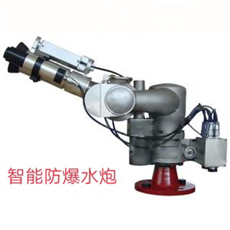
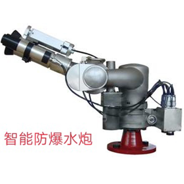
24. Auto-tracking jet fire suppression device with laser red dot aiming head, point and shoot, human-machine integration for enhanced reliability.
25. The main unit of the automatic tracking and positioning jet fire extinguishing device is equipped with a remote rod for real-time stepless speed control of the water cannon. Aim where you want to spray, and it can also be used as a quick ball for video surveillance during normal times.
26. The automatic tracking and positioning jet fire suppression device's moving parts are fully sealed, dust-proof, and capable of long-term automatic standby to protect the safety of the site.
27. The automatic tracking and positioning jet fire extinguishing device can be individually set to the automatic or manual status of four modes: water cannon, valve, pump, and laser, for convenient management.
28. The main unit of the automatic tracking and positioning jet fire extinguishing device can set a weekly calendar period for each cannon, automatically timing the switch between manual and automatic functions of the water cannon.
29. The main unit of the automatic tracking and positioning jet fire suppression system allows for operation of the water cannon, viewing, and adjusting water cannon parameters. It also enables remote programming for convenient maintenance and repair.
30. The core positioning component of the automatic tracking and positioning jet fire extinguishing device utilizes non-cooled focal plane infrared thermal imaging technology, offering image-based scanning. Once locked on, it provides real-time tracking of dynamic fire sources.
31. The Automatic Tracking and Locating Jet Fire Extinguishing Device System integrates three control methods: fire automatic alarm, on-site manual control, and centralized control from the central control room.
32. The Automatic Tracking and Positioning Jet Fire Extinguishing Device Water Gun Controller features a Chinese character color touch screen, with an integrated printer for real-time printing of alarm messages.
33. The automatic tracking and positioning jet fire suppression device comes with a four-axis remote rod for easy remote control of the water cannon's up, down, left, and right movements.
34. The automatic tracking and positioning jet fire suppression system features a timer conversion function. For each fire suppression device, multiple time periods can be set, and the system automatically completes the manual to automatic function conversion of the water cannon at the set time.
35. The automatic tracking and positioning jet fire extinguishing system features automatic interlock functionality, enabling automatic interlock between water cannons within the protected area—a single alarm activates the entire system.
36. The automatic tracking and positioning jet fire suppression device can be individually set to the automatic or manual status of the water cannon, valve, pump, and sound-lighting modes, facilitating management.
37. The automatic tracking and positioning jet fire extinguishing device features an interior observation point at each zone's exit where all fire hoses within the zone can be seen. An on-site operation panel is installed to control all water spray fire extinguishing settings within the zone. It displays nozzle selection, communication, audio-visual alarms, device fault indication, and silence status via Chinese LCD. Functions such as up, down, left, right direction, valve and pump on/off operations are performed through buttons. The on-site operation panel should be installed at a height of 1.5 meters from the ground, with no obvious obstructions around it.
38. The water cannon controller for the automatic tracking and positioning jet fire suppression system allows for remote viewing and adjustment of all parameters, as well as remote updating of the water cannon's software.
39. The operating parts of an automatic tracking and positioning jet fire suppression device should be fully sealed, with no gears visible at the openings to prevent dust from entering and affecting its long-term stable operation.
40. The fire extinguishing components of an automatic tracking and positioning jet fire suppression system should be integrated with a laser red dot indicator equipment for easy verification of the accuracy of the positioning at any time.
41. The Automatic Tracking and Locating Jet Fire Extinguishing Device employs masterless bus communication technology, with a single loop supporting up to 9,999 bus devices. The first two digits indicate the zone number, while the last two digits represent the cannon number.
42. The automatic tracking and positioning jet fire extinguishing device features a single outlet, concentrating water flow, with strong penetration power on the fire scene, difficult to atomize, and excellent in extinguishing early-stage fires.
43. The signal bus of the automatic tracking and positioning jet fire suppression device must be hand-in-hand structured without any branches.
44. The video cable for the automatic tracking and positioning jet fire suppression device is a point-to-point structure. Each water cannon has a separate video cable directly connected to the video host. When the distance exceeds 300 meters, fiber optic transmission should be used, with an optical-electric repeater for transmission.
45. The automatic tracking and positioning jet fire extinguishing system wiring is laid using metal pipes or metal conduits. Wires of different systems and voltages must not be installed in the same conduit or conduit channel. The power supply for the system should use AC220 fire protection power source, and power should not be taken locally.
46. Each fire compartment in the installation site of the automatic tracking and positioning jet fire extinguishing device should be equipped with at least one local operation panel. Connected via CAN bus, the main unit remotely monitors the fire scene in conjunction with the on-site video monitoring system, enhancing the function of linkage and decision management.
47. Fire hoses with automatic tracking and positioning jet fire suppression, on-site operation panels, and intelligent end-of-line water test devices, each occupy a single bus address point. They are all connected in parallel to the CAN bus without any branching in between.
48. The video cable for the automatic tracking and positioning jet fire extinguishing device follows the same wiring method as the security system, which is to run a video cable from the video host to each fire extinguishing device. The video cable should be a SYV75-5 cable. When the length of the video cable exceeds 300 meters, video transmission should be carried out using fiber optics.
49. To connect the automatic tracking and positioning jet fire extinguishing device's water cannon to the fire alarm system, simply add an input module to the passive alarm terminal of each water cannon's electrical control box to upload the water cannon's alarm signal to the fire alarm system; adding an input/output module will enable the fire alarm联动 to activate the water cannon.
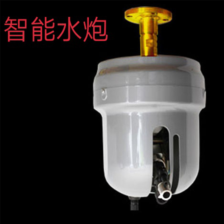
50. The water cannon of the automatic tracking and positioning jet fire suppression device can be installed by overhead, suspended, or mounted against the wall. Regardless of the installation method, ensure the nozzle is vertically downward and freely rotating. A DN50 flange is pre-installed 50cm from the wall or other obstructions, sealed with a rubber flat washer; metal washers are strictly prohibited. During installation, temporarily install two downward bolts on the upper flange first. Once the nozzle is close, secure the water cannon with two nuts, place the flat washer, then thread the nuts upward into the opposite bolt holes, tighten the nuts on top, and finally adjust the original downward bolts to face upward and tighten them.