


Circular Saw Table Specifications and Structural Features
I. Equipment Overview
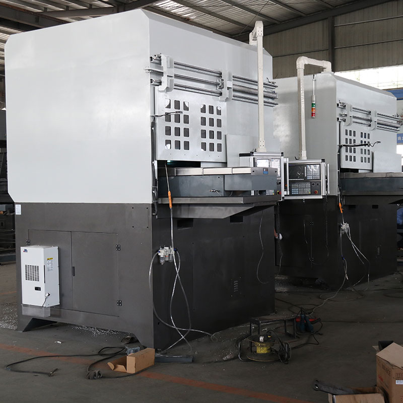
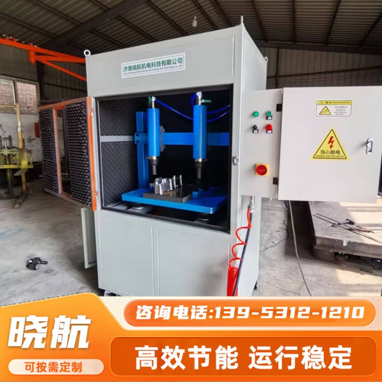
This series of machine tools is mainly used for sawing the sprues of aluminum casting on casting islands, featuring high cutting efficiency, energy saving, and simple operation.
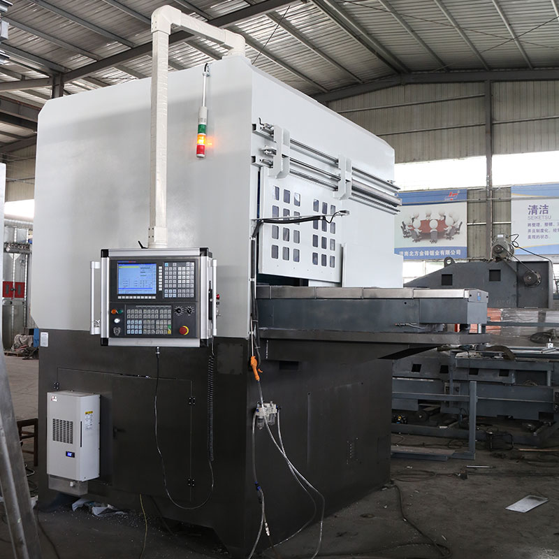
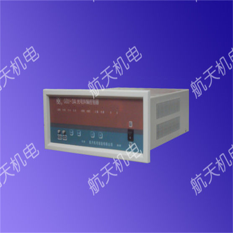
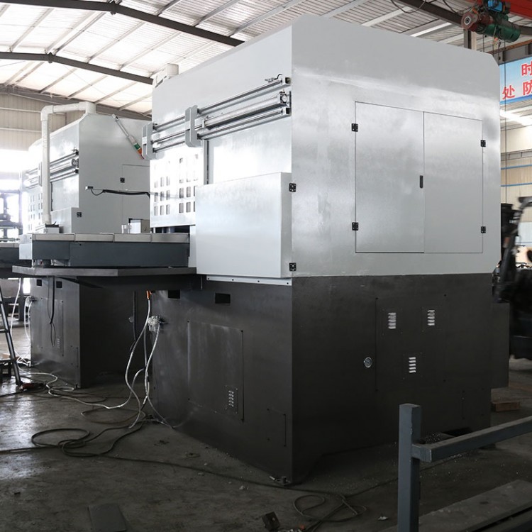
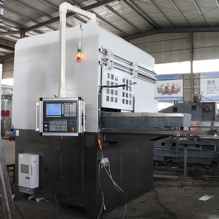
This machine tool features a fully enclosed structure for processing, utilizing circular saw blades as cutting tools. It is controlled by a CNC numerical control system, enabling signal interaction with the feeding robot for automated sawing process. The sawing speed is controlled via the CNC system.
II. Performance Features
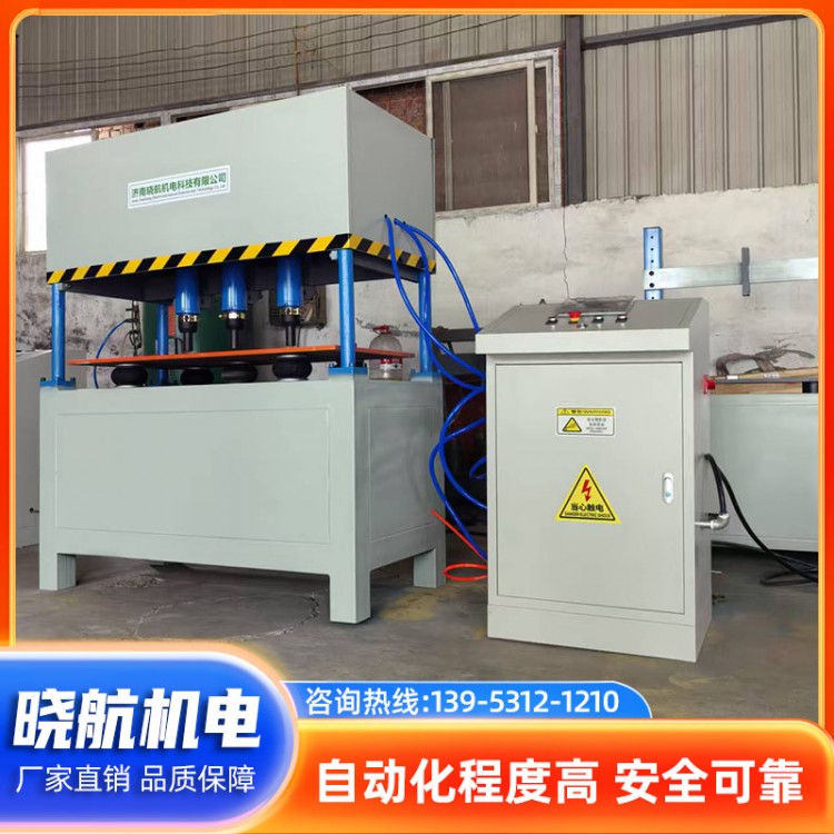
1. Designed specifically for cutting aluminum risers, featuring CNC system control for high precision and easy operation.
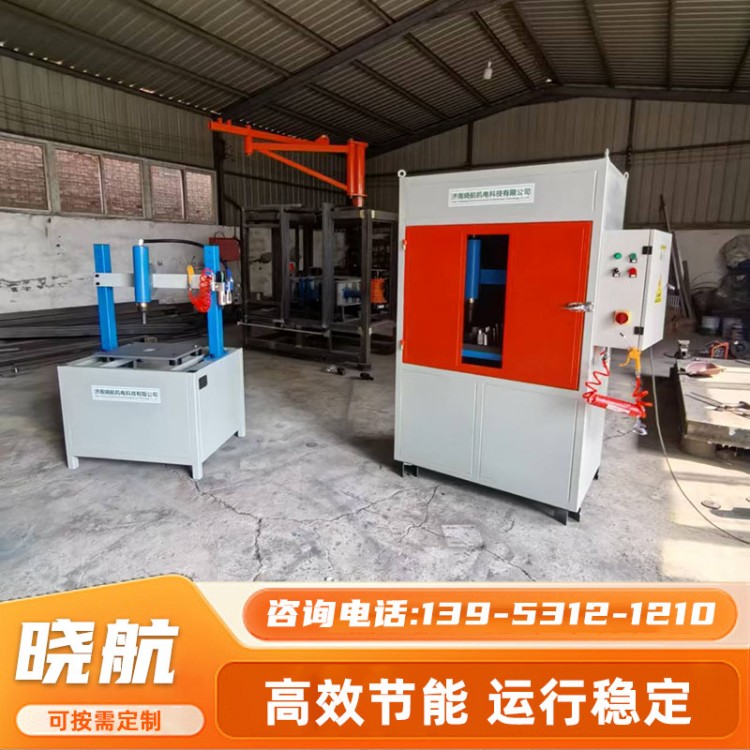
2. Double-column structure with linear guide rail guidance, offering stable and reliable guidance. The fixture features a 90° flip design, allowing for the cutting requirements to be met with a single clamping operation.
3. Servo motor drives the cutting motor to move along the Z and X axes for quick approach and positioning of the workpiece. The Y-axis servo motor feeds the workpiece, and after the fixture is flipped 90°, the Y-axis and Z-axis联动 allows for bevel cutting along the workpiece contour. Rapid feed and work feed. The transition between actions is stable, agile, and reliable.
4. The cast sprues are directly slid into the iron frame for collection via an incline.
5. Full machine exterior protection, with an additional feeding station on the cover for easy robot loading.
6. Fault alarm device, quick diagnosis of faults, easy for maintenance and repair.
7. Guideway screw is centrally lubricated with an automatic lubrication pump.
8. Equipped with an air gun for easy chip removal
9. To ensure the stable performance of the entire machine, all components used are from renowned brands both domestically and internationally. The main parts of the machine undergo thermal aging treatment to guarantee the stability of the minimum geometric deformation size.
III. Brief Description of Equipment and Tooling Process
1. The workbench's starting position is on the outer side of the guard, serving as the loading and unloading station.
2. The robot (with the workbench at the feeding station, no materials on the cutting fixture) places the workpiece onto the fixture and the clamping mechanism secures it (the equipment receives the signal indicating the robot has completed the feeding process).
3. The Y-axis drives the workbench workpiece into the equipment's cavity, while the Z-axis and X-axis position the material handle for sawing.
4. Cutting motor starts; Y-axis feeds and cuts off the handle.
5. The Z-axis and X-axis drive the cutting motor backward to a safe position
6. Gear Flip 90°
7. X-axis riser location
8. The Z-axis and Y-axis联动 cut runners along the workpiece contour
9. Cut motor stops, fixture resets, and Y-axis with workpiece returns to feeding position
10. Release the clamp and send the material pick-up signal to the robot