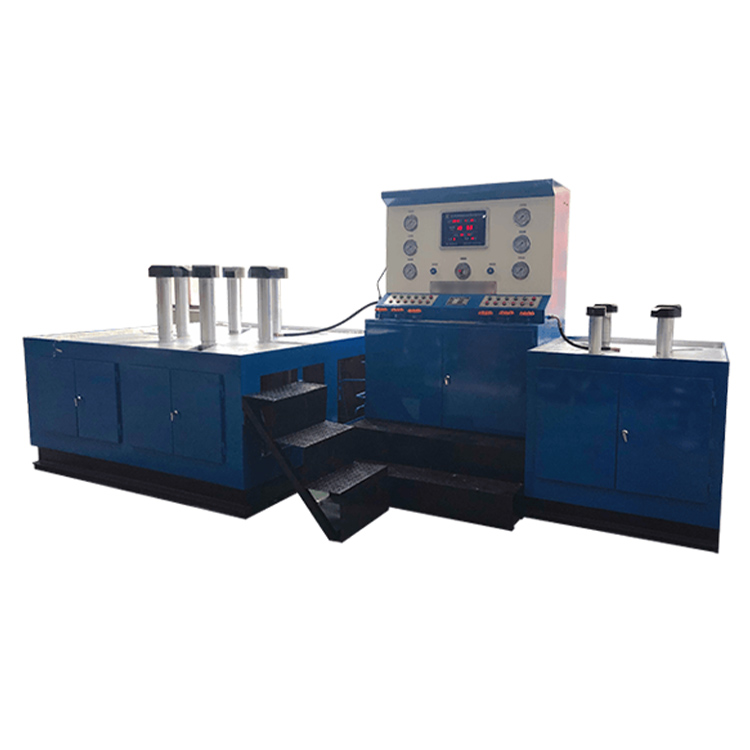


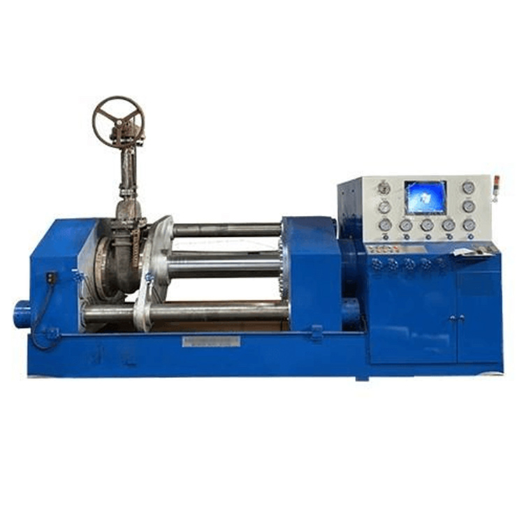

The DYFJ-H1200 type valve testing bench is the fourth generation pressure testing and detection equipment developed independently by Duojia Hydraulic Co., Ltd., based on many years of production experience and in accordance with national standards and specifications.
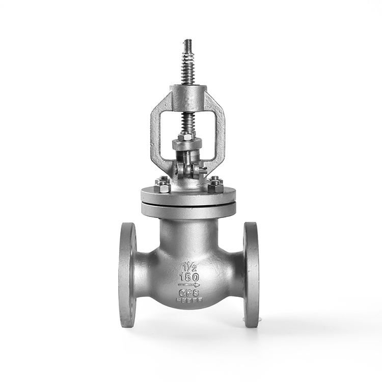
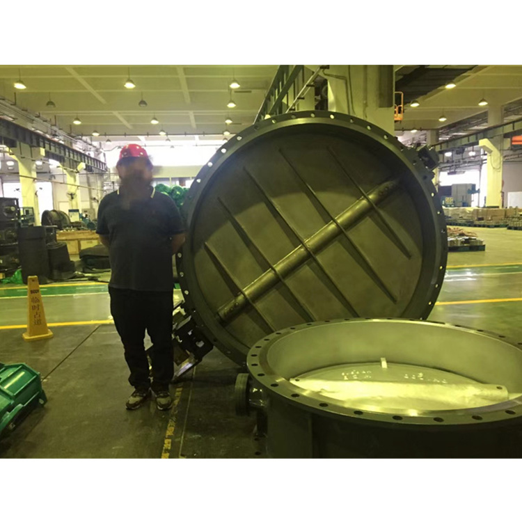
The DYFJ-H1200 type valve test bench integrates mechanical and electrical, hydraulic systems, pressure testing, and the storage and recycling of liquid media. It features comprehensive functions, stable performance, and high automation levels. It is widely used for sealing surface leakage testing and other performance tests, such as shell strength (pinhole), on various high, medium, and low-pressure valves with nominal bore sizes of 300-1200mm and direct flange connections. Test media: water, gas, oil.
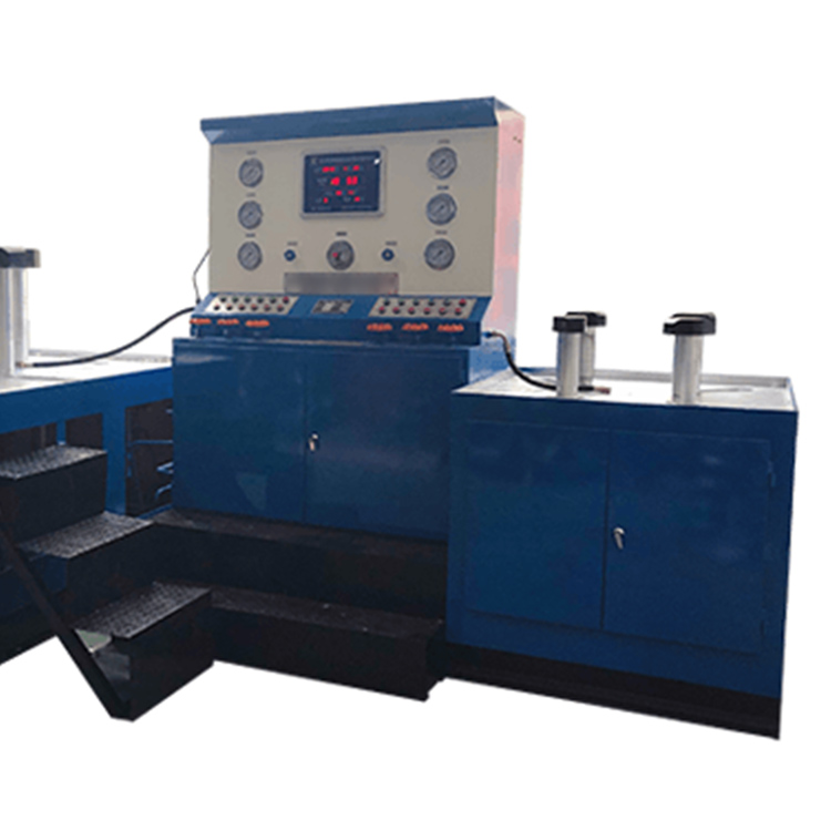
The equipment is hydraulically driven and electrically controlled throughout the process, with no external force affecting the valve test results, significantly enhancing work efficiency and reducing labor intensity. It is the ideal new generation valve pressure testing equipment for valve manufacturing enterprises, users, and maintenance units.
DYFJ-H1200 type valve test bench working principle and structure
The DYFJ-H1200 type valve testing bench operates by positioning the valve flange and clamping the back of the flange with movable claws, ensuring no external forces affecting the test results that could compromise the valve testing, in compliance with national standard valve testing requirements.
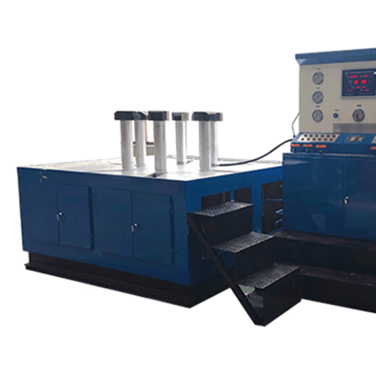
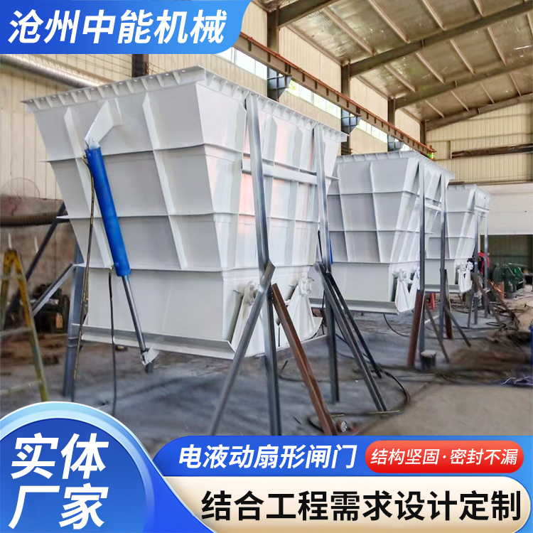
The equipment is roughly divided into hydraulic pressure supply systems, electrical control systems, water circulation systems, and various operating devices.
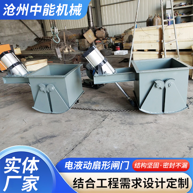
The equipment is of clamping type, with each side of the workbench sealed with a blind flange. The hydraulic gripper features axial extension and radial movement, directly driven by a hydraulic cylinder, ensuring uniform force distribution on the valve sealing surface for reliable clamping. When testing the butterfly valve, the sealing performance can be observed directly, facilitating the inspection of air tightness tests and the observation of the valve sealing surface. It boasts excellent performance and a simple, compact structure.
Operation Instructions
1. Valve Mounting Method
Select a valve with a nominal bore that matches the equipment model, turn on the power, and start the hydraulic system. Move the hydraulic actuating claw radially to exceed the outer diameter of the test valve flange, and extend it axially to exceed the valve length. Place the lower flange of the valve against the test bench blind plate, aligning with the center opening. Move the radial claw close to the valve flange, and extend the axial claw to make the claw tightly abut the valve flange face. At this point, the valve is securely gripped and fixed by the clamping system, ensuring that the valve will not vibrate.
During the strength test of the valve body, the other end of the valve to be tested is tightly sealed against the upper test blind flange, aligned with the center opening. Radially move the clamping jaws close to the valve flange. Axially move the clamping jaws to make the jaws tightly adhere to the back of the valve test blind flange. At this point, the valve should be securely held and fixed by the clamping system, with the valve in a stable overall state.
2. Water Pressure Testing Methods (Double-directional Inflow, Drainage)
After the valve mounting is complete, refer to the "Clamping Cylinder Pressure Reference Table" to increase the hydraulic clamp force to the required pressure. Adjust the electrical contact pressure gauge (for a 25 kg valve, adjust the gauge pointer to 2.5 MPa). Open the main inlet and left and right inlet valves, close the air intake, drain water, and exhaust valves. Start the low-pressure water pump, observe the movement of the water pressure gauge pointer. When the pointer stops rising, it indicates that the valve cavity is full of water. Start the high-pressure water pump; when the water pressure reaches the pressure set on the electrical contact pressure gauge, the high-pressure water pump automatically stops, and the equipment enters the water pressure maintenance state.
Upon reaching the pressure-holding time, the valve shows no issues. It should first be opened to release the water pressure within the valve chamber, and then the valve can be removed.
3. Pressure Testing Methods (Bi-directional Intake, Venting)
The equipment does not come with a gas source. The user must provide their own. Please consult the manufacturer before using high-pressure gases.
After the valve clamp is completed (using pressure air as an example, generally not exceeding 10 kg of pressure), open the water and air intake valves, and close the water and air exhaust valves. Close the water and air intake valves when the pressure gauge reaches the highest pressure, and the equipment remains in a pressure maintenance state.
Upon reaching the pressure-holding time, the valve is free of any issues. It should first be opened to release the pressure inside the valve chamber before removing the valve.
Handling Instructions and Requirements
1. Align the equipment horizontally during installation or secure the anchor slot with concrete.
2. Use 46-grade anti-wear hydraulic oil (for temperatures below 0°C, use anti-freeze 46-grade anti-wear hydraulic oil). The oil level must not be below the indicator's lower limit. Regularly check the oil level and hydraulic oil. After one year of use, clean the oil tank and replace the hydraulic oil.
3. Add rust inhibitor to the recirculating water, and replace the water promptly when the water quality deteriorates.
4. The equipment work surface should be kept clean, and there should be no debris between the test valve flange and the test pressure blank flange.
5. All moving parts of the test bench should be lubricated and kept clean for smooth operation.
6. Operators must undergo professional training prior to assuming their positions, ensuring standardized procedures and safety precautions.