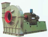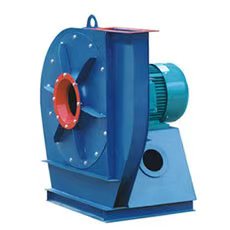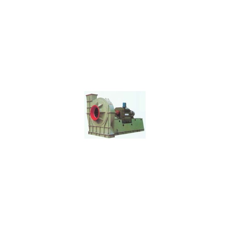


M7-29 Coal Powder Centrifugal Blower

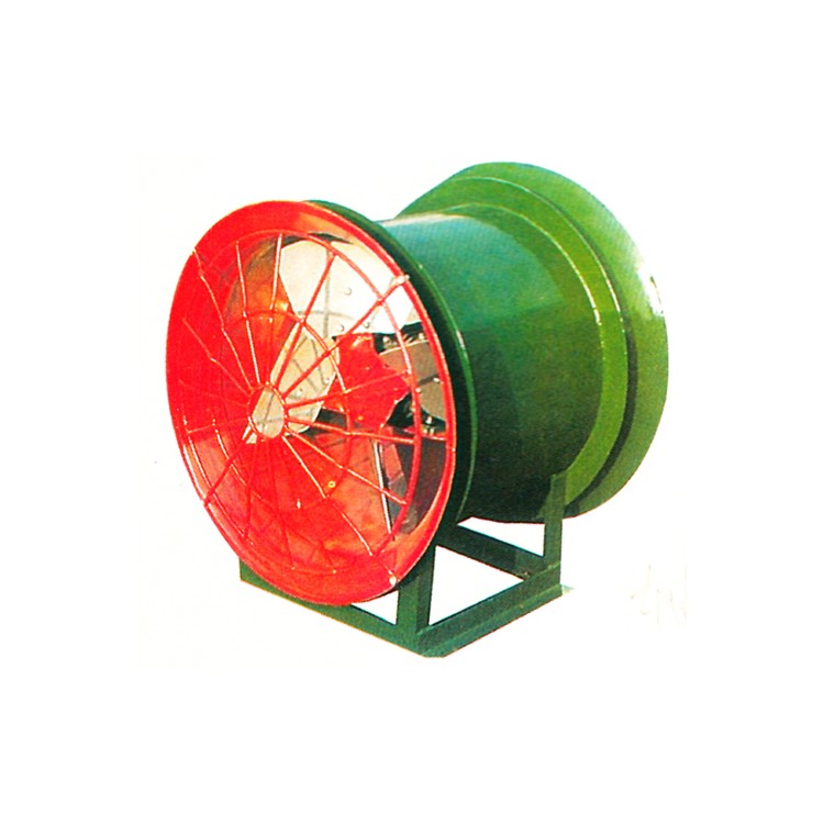
I. Usage
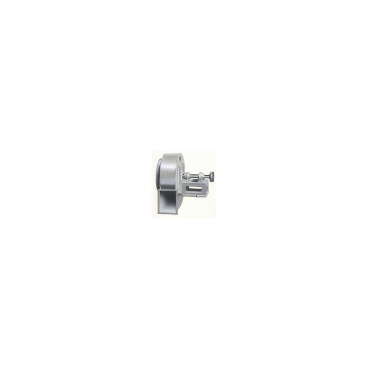
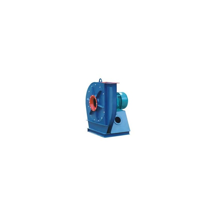
The M7-29 type coal powder centrifugal blower is designed to meet the performance requirements of the coal powder combustion system in thermal power plant boilers. It is used to blow coal powder into the boiler; the coal powder cannot pass directly through the impeller, as it would lead to easy wear and tear. The casing is internally lined with protective plates for easy replacement after wear. The bearing housing contains lubricating oil to dissipate heat from the bearings, and is equipped with a cooling water pipe to cool the lubricating oil.
Two,M7-29 Coal Powder Centrifugal Blower Performance Parameters Table
Parameters provided in the performance table, with the calibrated working conditions being: atmospheric pressure of101,325 Pa, intake temperature of 70°C, medium gas (air) density of 1.02 kg/m³.
Engine number | Impeller | Air Inlet | Air outlet | C | D | E | F | G | |||||||||||
A1 | A2 | A3 | d1 | n1 | B1 | B2 | B3 | B4 | B5 | B6 | d2 | n2 | |||||||
11D | 1100 | φ590 | φ640 | φ690 | M16 | 16 | 300 | 363 | 412 | 484 | 550 | 664 | φ14.5 | 16 | 178.5 | 144.5 | 750 | 820 | 944.5 |
12.5D | 1250 | φ670 | φ720 | φ770 | M16 | 16 | 340 | 412 | 476 | 550 | 630 | 694 | φ14.5 | 18 | 197 | 163 | 850 | 931 | 1075.5 |
13D | 1325 | φ710 | φ770 | φ830 | M16 | 16 | 360 | 440 | 502 | 580 | 670 | 731 | φ14.5 | 18 | 208 | 171 | 890 | 980 | 1135.5 |
14.5D | 1450 | φ778 | φ838 | φ898 | M16 | 16 | 395 | 480 | 550 | 632 | 720 | 798 | φ14.5 | 18 | 222 | 188 | 972 | 1076.5 | 1248.5 |
16D | 1600 | φ850 | φ920 | φ990 | M16 | 16 | 494 | 580 | 638 | 750 | 847 | 898 | φ19 | 24 | 246 | 208 | 1250 | 1190 | 1360 |
17D | 1700 | φ900 | φ970 | φ1040 | M16 | 16 | 534 | 618 | 674 | 834 | 924 | 982 | φ19 | 26 | 259 | 221 | 1450 | 1262 | 1440 |
H | I | J | K | a | b | L | d | d3×L1 | d4×L2 | Cooling Tube | Bearings | Weight (without power) | P1 | P2 | Turn | Blade wheel | |||
738.5 | 642.5 | 375 | 1196 | 620 | 700 | 762.5 | 375 | M24×630 | M20×500 | φ18 | 3616 | 1055 | 540 | 458 | 100 | 191 | |||
837 | 730 | 375 | 1196 | 620 | 700 | 785 | 412 | M30×800 | M24×630 | φ18 | 3620 | 1530 | 707 | 895 | 210 | 274 | |||
880 | 770 | 375 | 1196 | 620 | 700 | 793 | 432 | M30×800 | M24×630 | φ18 | 3620 | 1555 | 846 | 753 | 380 | 300 | |||
967.5 | 849.5 | 500 | 1620 | 900 | 900 | 1057.5 | 466 | M30×800 | M24×630 | 1.25" | 36226 | 2100 | 980 | 860 | 540 | 405 | |||
3526 | |||||||||||||||||||
1070 | 911 | 500 | 1549 | 900 | 900 | 1008.5 | 510 | M30×800 | M24×630 | 1.25" | 36226 | 2566 | 1482 | 1355 | 840 | 496 | |||
3526 | |||||||||||||||||||
1134 | 949 | 500 | 1549 | 900 | 900 | 1008.5 | 536 | M30×800 | M24×630 | 1.25" | 36226 | 2810 | 1631 | 1419 | 950 | 590 | |||
III. Type
This fan is a single-inlet type, consisting of six models: M7-29№11, 12.5, 13, 14.5, 16, and 17.
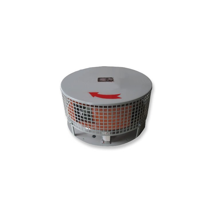
⑵ This fan is available in two types: clockwise rotation and counterclockwise rotation. When viewed from the positive end of the motor, the impeller rotating in the clockwise direction is referred to as a clockwise-rotating fan, indicated by "clockwise"; and the impeller rotating in the counterclockwise direction is called a counterclockwise-rotating fan, indicated by "counterclockwise."
③ The outlet position of the fan, expressed in the angle of the air outlet of the housing, with a total of 16 specifications ranging from 0° to 225°.
Installation, Calibration, Operation, Maintenance
The fan must be installed according to the specified procedures, and only after a trial run can it be officially put into production.
If an abnormal condition is detected during the operation of the fan, the machine should be immediately shut down to investigate the cause. The fault should be eliminated before resuming operation.
The bearing housing of the fan uses water-cooling, with the water pressure not exceeding 0.4Mpa. Due to varying temperatures in different regions and seasonal changes, the water flow rate can also vary. Generally, the water flow can be considered at 0.5 to 1 m3/h. At the same time, attention should be paid to the water quality to prevent scaling and blockage within the passage, which may affect the cooling efficiency.
If the fan blade is worn, it should be rebalanced after welding and repair.
The bearing temperature of the fan is generally not higher than 40°C above the ambient temperature.
The fan should be regularly inspected according to usage conditions.
Item 7: The operating speed of the fan must not exceed the permitted operating speed, and variable-speed using a wheel is not allowed.
Lubricate bearings with thin oil, recommend using N32 mechanical oil.
During normal operation, the effective vibration velocity (root mean square) of the bearing housing is ≤6.3 mm/s.
V. Order Instructions
Complete supply scope: 1 fan, 1 motor, 1 set of couplings, 8 sets of fan foot bolts.
⑵ Users should specify the fan name, model, rotation direction, and outlet angle; performance parameters (flow rate, total pressure, motor model, power, speed, voltage).
Engine Number | Blade Wheel | Air Inlet | Air outlet | C | D | E | F | G | |||||||||||
A1 | A2 | A3 | d1 | n1 | B1 | B2 | B3 | B4 | B5 | B6 | d2 | n2 | |||||||
11D | 1100 | φ590 | φ640 | φ690 | M16 | 16 | 300 | 363 | 412 | 484 | 550 | 664 | φ14.5 | 16 | 178.5 | 144.5 | 750 | 820 | 944.5 |
12.5D | 1250 | φ670 | φ720 | φ770 | M16 | 16 | 340 | 412 | 476 | 550 | 630 | 694 | φ14.5 | 18 | 197 | 163 | 850 | 931 | 1075.5 |
13D | 1325 | φ710 | φ770 | φ830 | M16 | 16 | 360 | 440 | 502 | 580 | 670 | 731 | φ14.5 | 18 | 208 | 171 | 890 | 980 | 1135.5 |
14.5D | 1450 | φ778 | φ838 | φ898 | M16 | 16 | 395 | 480 | 550 | 632 | 720 | 798 | φ14.5 | 18 | 222 | 188 | 972 | 1076.5 | 1248.5 |
16D | 1600 | φ850 | φ920 | φ990 | M16 | 16 | 494 | 580 | 638 | 750 | 847 | 898 | φ19 | 24 | 246 | 208 | 1250 | 1190 | 1360 |
17D | 1700 | φ900 | φ970 | φ1040 | M16 | 16 | 534 | 618 | 674 | 834 | 924 | 982 | φ19 | 26 | 259 | 221 | 1450 | 1262 | 1440 |
H | I | J | K | a | b | L | d | d3×L1 | d4×L2 | Cooling Tube | Bearings | Weight (without power) | P1 | P2 | Turn | Impeller | |||
738.5 | 642.5 | 375 | 1196 | 620 | 700 | 762.5 | 375 | M24×630 | M20×500 | φ18 | 3616 | 1055 | 540 | 458 | 100 | 191 | |||
837 | 730 | 375 | 1196 | 620 | 700 | 785 | 412 | M30×800 | M24×630 | φ18 | 3620 | 1530 | 707 | 895 | 210 | 274 | |||
880 | 770 | 375 | 1196 | 620 | 700 | 793 | 432 | M30×800 | M24×630 | φ18 | 3620 | 1555 | 846 | 753 | 380 | 300 | |||
967.5 | 849.5 | 500 | 1620 | 900 | 900 | 1057.5 | 466 | M30×800 | M24×630 | 1.25" | 36226 | 2100 | 980 | 860 | 540 | 405 | |||
3526 | |||||||||||||||||||
1070 | 911 | 500 | 1549 | 900 | 900 | 1008.5 | 510 | M30×800 | M24×630 | 1.25" | 36226 | 2566 | 1482 | 1355 | 840 | 496 | |||
3526 | |||||||||||||||||||
1134 | 949 | 500 | 1549 | 900 | 900 | 1008.5 | 536 | M30×800 | M24×630 | 1.25" | 36226 | 2810 | 1631 | 1419 | 950 | 590 | |||