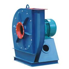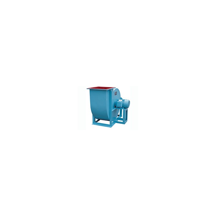


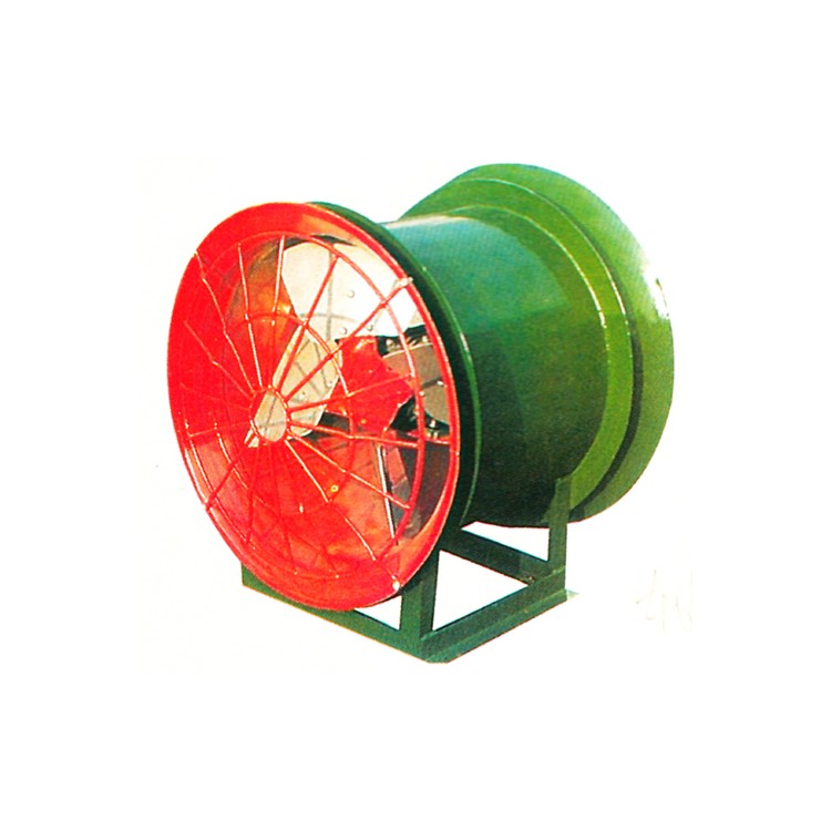
C5-51 Dust Extraction Centrifugal Blower

Purpose
The C5-51 type dust centrifugal blower is suitable for conveying air mixtures containing wood chips, fibers, dust, and the like.
Model
In general, the C5-51 centrifugal fan comes in 7 model numbers: No. 3.15, No. 4, No. 5, No. 6.3, No. 8, No. 10, and No. 12.5. Any model can be manufactured in either left-hand or right-hand rotation. When viewed from the positive side of the motor, clockwise rotation is referred to as "right-hand fan," indicated by "R," while counterclockwise rotation is called "left-hand fan," indicated by "L."
The outlet position of the fan is indicated by the outlet angle of the housing. The adjustment range of the outlet is 0° to 225°, with an interval of 45°.
The above air outlet angle is a common practice in the fan industry. If these practices do not meet your specific application environment and conditions, our factory can customize the angle to your satisfaction. In such cases, the installation size chart at the end of this manual may vary. Users are advised to pay attention.
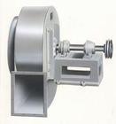
The fan's drive type is C-style.
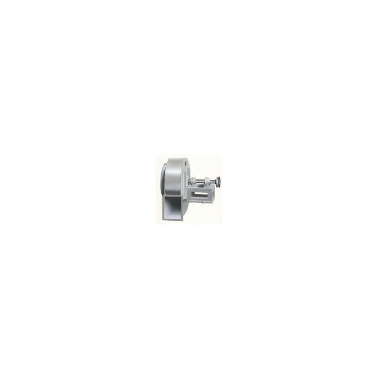
C-1 represents the cantilever support unit, belt-driven, but the belt pulley is on the outside of the bearing.
These transmission methods generally meet the users' requirements. In the unlikely event they do not, our factory has the capability to design and produce a fan that will satisfy you.
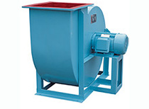
Structure
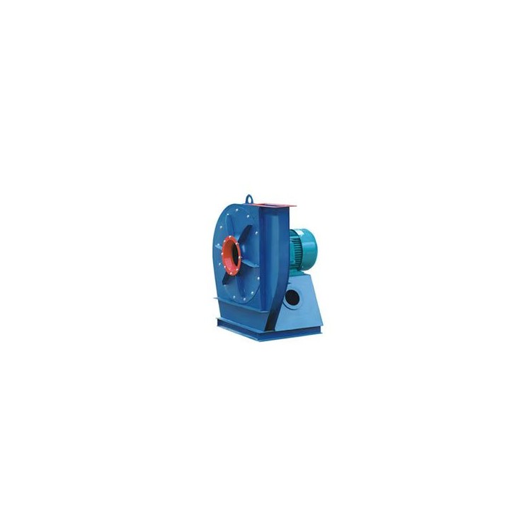
Fans are generally composed of blades, housing, inlet, and drive components.
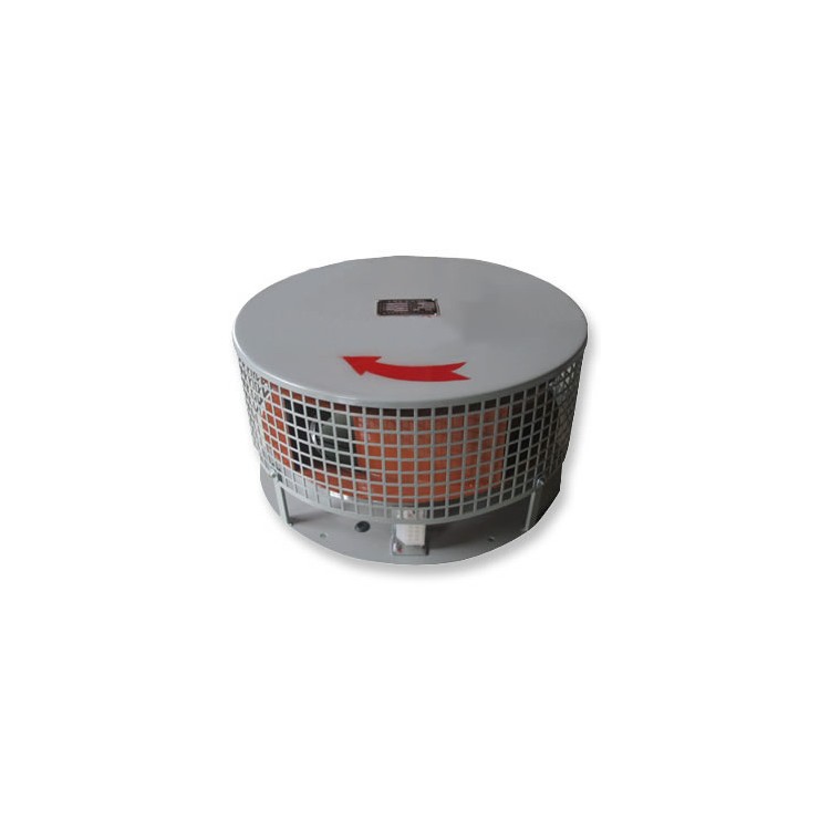
Blade: It is the core component of the fan, with its material and profile determining the fan's wind pressure, airflow, energy consumption, noise level, and lifespan. This fan is composed of ten rear-tilted arc-shaped blades, a curved wheel cover, and a flat rear disk. After dynamic and static balance correction and high-speed operation tests, it operates smoothly and reliably with excellent air performance.
Casing: The casing is a single unit and cannot be disassembled. The specific material depends on the purpose of the fan, and can be welded from ordinary iron plate, stainless steel, or processed from fiberglass. Of course, the process, cost, and timeline will vary accordingly.
Inlet: The inlet is designed as a monolithic structure with a curved cross-section parallel to the axis, facilitating smooth gas entry into the impeller with minimal loss. The inlet is typically secured to one side of the fan with bolts. Inadequate radial and axial gaps between the inlet and the impeller can cause friction if too small, or air leakage if too large, affecting efficiency. Please ensure the design dimensions are accurate.
Transmission: The transmission section consists of the main shaft, bearing housing, roller bearings, and belt pulleys.