


GDF Type Centrifugal Pipeline Fan

【Product Application】 Widely used in hotels, shopping malls, cinemas, auditoriums, colleges and universities, and scientific research institutions.
Model: GDF1.4-5.0
[Performance and Specifications] See parameter table
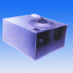
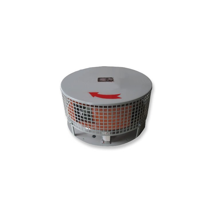
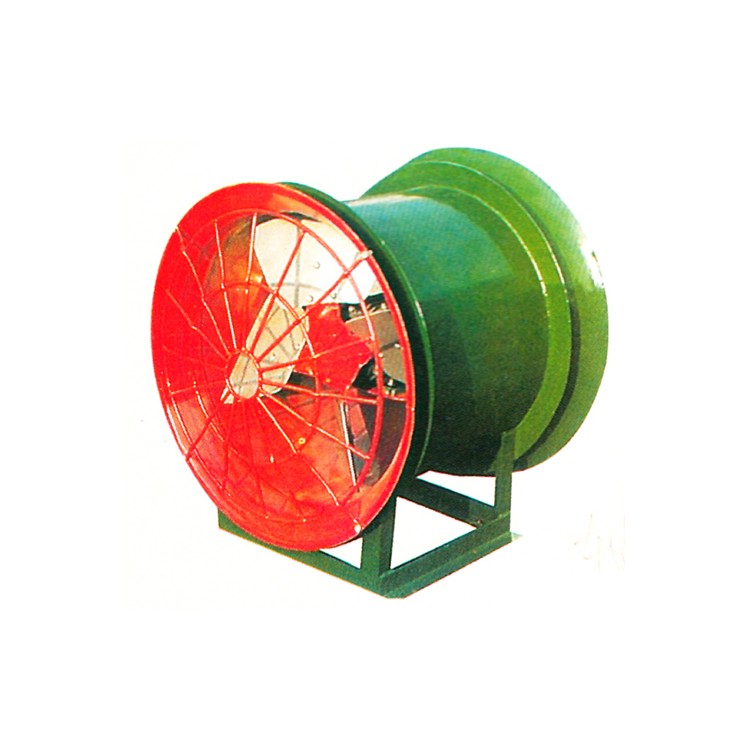
The GDF series centrifugal pipeline fan impellers consist of multiple forward-curved aluminum alloy blades, a front disk, and a rear disk. The housing is made by spot welding after being mechanically and mold processed from galvanized steel plate or stainless steel, featuring low noise, low vibration, and a rational structure.
Fan structure
1. The impeller features multiple forward-curved aluminum alloy blades, with both the front and rear disks manufactured using mechanical molds and verified for static and dynamic balance, ensuring smooth and reliable operation with excellent aerodynamic performance. 2. The housing is made of galvanized steel sheets, formed by mechanical molds. 3. The motor bracket is also made of galvanized steel sheets, formed using mechanical molds. 4. All motors are equipped with a single-bearing external rotation motor, with the impeller mounted on the motor housing. The motor bracket is fixed to the top plate of the housing, driving the impeller directly through the rotation of the motor housing.
Terms of Use
1. Types of gases conveyed: Air and other non-flammable, non-corrosive, and non-harmful to humans gases. 2. Contaminants in the gas: No sticky substances are allowed in the gas, and the dust and coarse particle content should not exceed 100mg/m3. 3. Gas temperature operating range: -20℃ to 80℃. 4. This series of fans is only suitable for indoor installation and should be mounted according to the orientation shown on the sample cover. Do not install it upside down or on its side; otherwise, it may affect the motor's lifespan. If outdoor installation is necessary, consider the motor's rainproof measures.
Design Selection Instructions
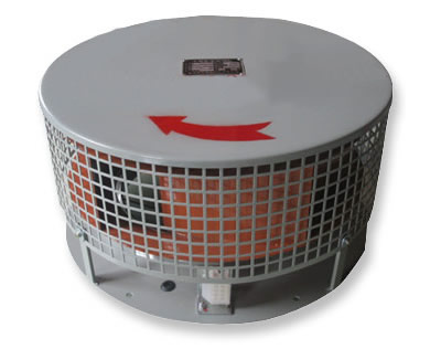
1. This pipeline fan is a forward multi-blade centrifugal fan. Its noise is significantly lower than that of an axial fan under the same air volume and pressure conditions. The air volume, pressure, and noise parameters of this series of fans are designed based on many actual engineering needs and are widely applicable to public place ventilation and exhaust systems. 2. An arrow indicating the exhaust direction is marked on the top surface of the fan housing, which can prevent reverse installation and ensure the normal operation of the ventilation and exhaust system. 3. Insulation should be designed when there is a possibility of condensation on the outer surface of the housing and pipeline due to the transmission of low-temperature air. 4. The noise level of the fan is the average value measured one meter from the inlet when the rated air volume and pressure are not connected to the air duct. If both inlet and exhaust ducts are fitted, the noise level will decrease. For applications with high noise requirements, noise-reducing elbows or mufflers should be installed on the inlet and exhaust ducts. 5. The power connection diagram for the single-phase (220V) motor used with the fan is placed inside the fan power connection box. 6. The fan operates with minimal vibration, generally requiring no vibration reduction measures. If the design deems it necessary, vibration-reducing rubber pads or springs can be added or removed at the fan supports. 7. When installing the fan, the distance between the fan and the ceiling must be considered for easy disassembly during maintenance. The distance between different model fans and the ceiling is detailed in the following chart.