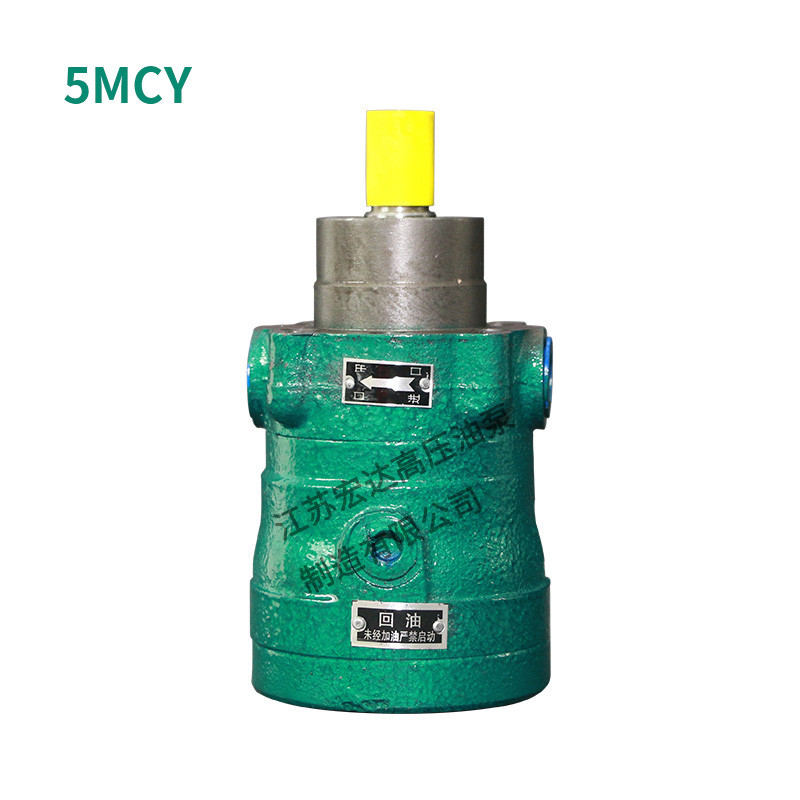


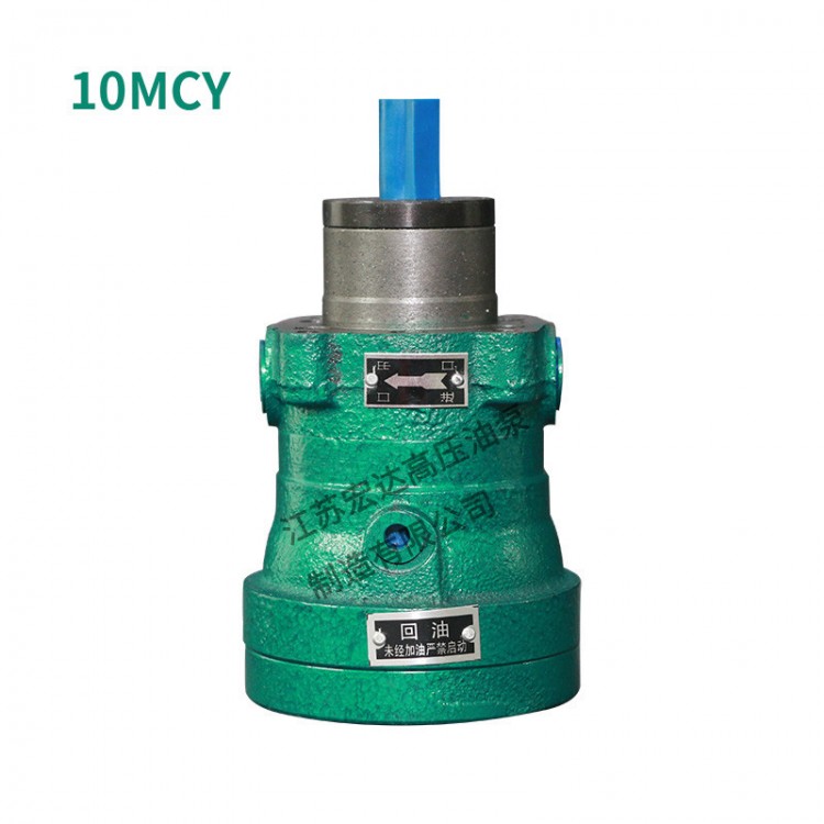


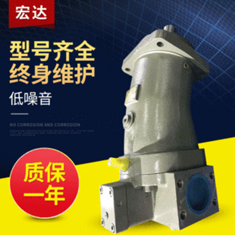
MCY14-1B Axial Piston Pump
CY14 Axial TypePlunger pumpIt is an axial piston pump that uses a distribution plate for oil distribution and cylinder rotation. Due to the hydraulic static balance structure between the sliding shoe and variable head, as well as between the distribution plate and cylinder, it boasts advantages such as simple structure, compact size, high efficiency, long service life, light weight, and strong self-priming capability when compared to other types of pumps. It is suitable for machinery such as machine tools, forging presses, metallurgy, engineering, mining, and other hydraulic transmission systems. This pump can also be used as a hydraulic motor by simply replacing the motor distribution plate.
Model Description
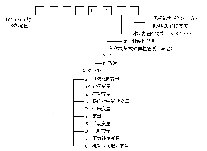
63SCY14-1B is a nominal flow of 63L/min at 1000r/min, manual variable in the forward rotation, cylinder rotationAxial Piston PumpType B Drawing
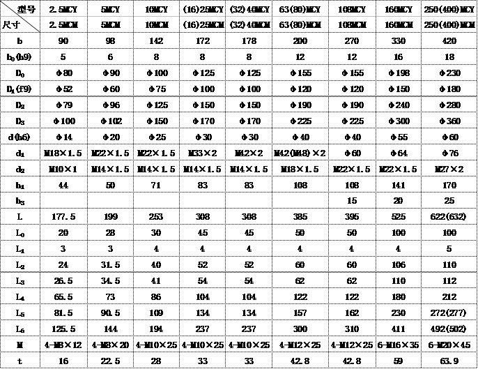
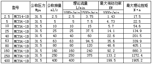
Series specifications
Terms of Use
Axial piston pumps are a precision component, and their correct usage directly impacts the pump's lifespan. Therefore, all users must strictly adhere to the following requirements for proper operation of the pump.
1. Installation
(1) The oil pump can be mounted with a bracket or flange. The pump and the prime mover should use a common foundation bracket. The bracket, flange, and foundation should all have sufficient rigidity to prevent vibration during the operation of the oil pump. For pumps with a flow rate of 160L/min or more, due to the higher power of the prime mover, it is recommended not to install them on the oil tank.
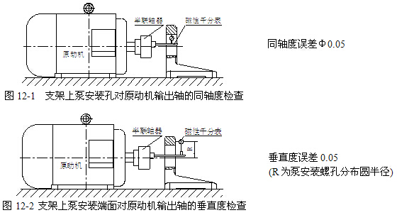
(2) The coaxial alignment error between the pump's drive shaft and the output shaft of the prime mover, as well as the method of alignment, is as follows:
A. Bracket Installation: The method for checking the installation accuracy of the output shaft of the prime mover with the bracket is shown in Figures 12-1 and 12-2.
B. Flange Installation: In this type of installation, if the prime mover and pump are connected by a coupling, the installation accuracy check method is as shown in the above figure. If the pump shaft is directly inserted into the output shaft of the prime mover, refer to Figures 13-1 and 13-2 for the installation accuracy check method.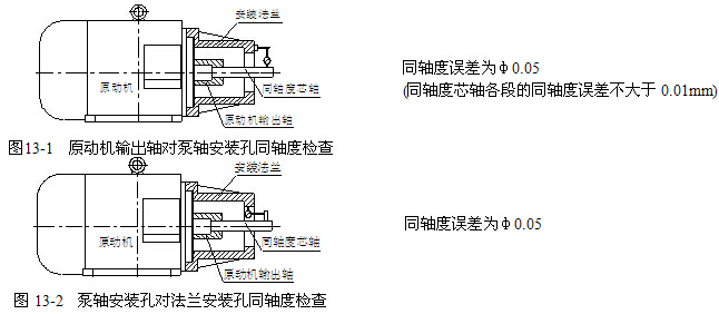
Verticality error is 0.05
(R is the diameter of the circular distribution of pump mounting holes)
(3) It is recommended to use an elastic coupling to connect the pump and the drive shaft of the prime mover as much as possible, as the pump's drive shaft cannot withstand bending moments. Therefore, it is strictly prohibited to install a belt or gear to drive the oil pump on the pump shaft. If it is necessary to connect the pump with a belt or gear, it is suggested to add a bracket to install the belt or gear (Figure 14).
(4) The rotation direction of the oil pump, as indicated by the pump's label. If the rotation direction is not specified during ordering, the supply will be made in a clockwise direction (as viewed from the shaft end). To change the pump's rotation direction, please contact the manufacturer.
(5) The installation of the oil pump should take into consideration ease of maintenance, allowing the variable housing to be easily removed, facilitating the extraction of the cylinder and oil-distributing plate inside the pump.
2. Fuel Tank Design
Due to the pump's use of static hydraulic bearings, strict attention must be paid to prevent oil contamination. The design quality of the oil tank significantly impacts contamination. The hydraulic pipeline should be thoroughly cleaned before installation, with steel pipes typically subjected to acid cleaning and neutralization treatment; cleaning should occur post-welding to ensure pipeline cleanliness. The oil tank design must be sealed to prevent continuous contamination.

Figure 14: Installation Methods for Pumps Driven by Belt Pulleys or Gears
Fuel Tank Design Key Points:
The fuel tank capacity, in an open-loop system, the effective volume (operational volume) of the fuel tank should be greater than three times the flow rate per minute of all pumps in the system. In a closed-loop system, the tank capacity can also be referred to the above principle, but the flow rate of the oil pump can be considered based on the flow rate of the replenishment pump. For systems with accumulator, the fuel tank should be able to accommodate the return oil volume of the accumulator. Additionally, the tank capacity should also consider the system's heat generation. If there are no strict requirements for the size and weight of the equipment, to enhance cooling efficiency, the fuel tank capacity can be appropriately increased.
To prevent continuous oil contamination, the oil tank must be strictly sealed. Oil that leaks onto the tank cap from the valve and pipes must not flow back into the tank. The internal tank is connected to the atmosphere via an air filter. The air filter must be cleaned simultaneously with the oil tank. The pipes inserted inside the oil tank must be sealed tightly with the tank top cover to prevent dust from entering.
The normal operating temperature for this pump is 10~65°C; if the temperature exceeds this range during use, a heating or cooling device must be installed in the hydraulic system.
3. Filter
The cleanliness of the working oil significantly affects the lifespan of the oil pump. baffles should be installed inside the housing to eliminate air bubbles during the return oil process, equipped with 80 mesh screens. The hydraulic system should be fitted with a 15μ to 20μ fine filter in the return oil section to maintain the cleanliness of the oil. (Do not install a fine filter on the pump's leakage oil pipe to prevent an increase in the pressure in the housing cavity, which could cause oil leakage at the skeleton seal. The intake pipe of the pump should not be fitted with an oil filter to avoid increasing the suction resistance.)
In addition to the requirements mentioned above, users must pay special attention to:
(1) Prior to installation and trial operation, the fuel tank, pipelines, cylinders, valves, etc., must be thoroughly cleaned. When refilling the fuel tank with new oil, it is also necessary to filter the oil using a filter oil machine to prevent contamination of the oil due to unclean oil drums.
(2) After one week of use, the new pump requires a full oil change, cleaning the oil tank and filter. Then, depending on the machine's workload, replace the oil filter with a 15μ to 20μ filter every 3 to 6 months, or change the oil and clean the oil tank.
(3) It is strictly prohibited to open the oil tank cover or oil filling hole due to system heating during use.
4. Self-priming and piping
When installing the oil pump, it's advisable to position the oil tank's liquid level above the pump's intake port as much as possible. For pumps with flow rates less than 160L/min, they can be installed on the oil tank for self-priming. For pumps with flow rates above 160L/min, back-priming for self-priming should be used. The diameter of the suction pipe should not be smaller than the recommended size, and the diameter of the shut-off valve should be one size larger than the intake pipe. The distance H1 from the end of the intake pipe to the side wall of the oil tank should be greater than 3D, and the distance H to the bottom of the oil tank should be greater than 2D; no more than two elbows should be used. Both the suction pipe and the leak pipe must be below the oil tank's low oil level by 200mm to prevent air from entering.
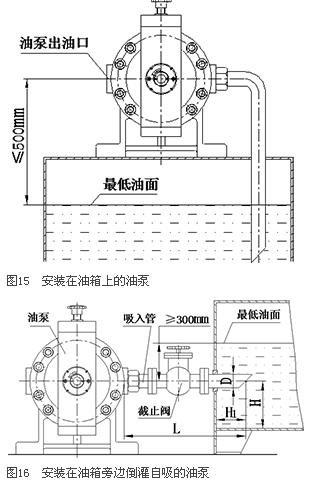
(1) Self-priming installed on fuel tank (Fig. 15)
a. The center height of the oil pump to the lowest oil level shall not exceed 500mm.
b. No oil filters are allowed to be installed on the intake pipeline.
c. If the oil pump needs to reduce the starting angle, it cannot guarantee self-priming (If the user requires a lower flow rate during operation, they should adjust the flow rate using a variable mechanism after the pump has started at full angle).
(2) Back-Flow Self-Priming (Fig. 16)
a. The distance from the low fuel level in the fuel tank to the center of the pump should be ≥300, and the pump can start self-priming with a slight angular deviation.
b. The oil pump intake pipe length L < 2500mm.
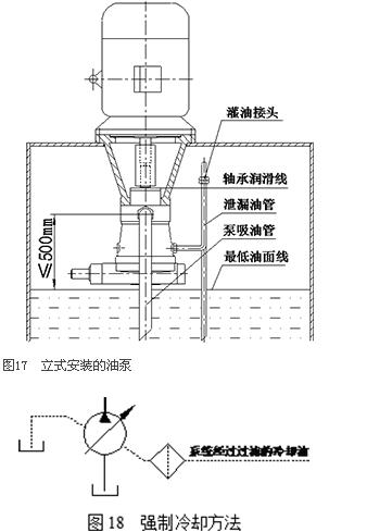
(3) Self-priming vertical-mounted oil pump (Fig. 17)
The distance from the oil pump inlet to the lowest oil level shall not exceed 500mm.
b. The filling connector on the leaking oil pipe should be higher than the oil pump bearing lubrication line (end flange cover).
5. Method for connecting the oil tube with leakage
(1) The oil drain port must be directly connected to the fuel tank and not to the system pipeline.
(2) When the pump frequently operates at zero deviation angle or the system working pressure is below 8MPa, causing excessive leakage and pump body heating, consider implementing cooling measures. Redirect a branch pipe from the system return oil line to the lower leakage oil port of the oil pump for forced circulation cooling (as shown in Figure 18). The oil pressure within the casing should be less than 0.05MPa.
(3) When using a supercharged oil tank due to the requirement of the hydraulic system, the pressure should not exceed 0.05 MPa.
6. Working Medium
(1) Recommend using domestic N32-46 hydraulic oil, or other hydraulic oils with a viscosity index of 3-5 and greater than 90, such as E50. The moisture, ash, and acid value in the oil must comply with the relevant specifications for hydraulic oil.
(2) The normal operating oil temperature for this pump is 10~65°C. If 10# aviation hydraulic oil is used, the performance of its cooling system must be excellent.
7. Initiate
(1) Check if the oil pump is installed correctly and reliably, and if the coupling is installed to specification. Rotate the coupling by hand to inspect if the pump shaft rotates evenly. Also, verify that the two couplings are aligned axially and if there is adequate axial clearance.
(2) Prior to initial use or after long-term storage before operation, it is mandatory to fill the pump with clean working oil through the leakage oil port on the pump housing before starting. Failure to do so is prohibited! Also, check the pump's rotation direction before starting!
(3) Adjust the system's relief valves to low values, strictly prohibit starting with load!
(4) Upon starting the pump, it should be manually operated first to ensure normal oil output, followed by continuous operation. After a period of operation without any adverse effects, gradually adjust to the desired pressure and flow rate. The pressure adjustment of the safety valve in the hydraulic system must not exceed 35 MPa.
(5) When a pump is restarted after being out of service for three months or more, it should first be operated at no load for half an hour. If abnormal temperature rise, leakage, vibration, or noise is detected during operation, the pump should be stopped immediately for inspection.
8. Load Operation
(1) Low-load Operation: After completing the aforementioned preparations, start the pump and operate it under a pressure of 1~2 MPa for half an hour.
(2) Full Load Operation: After the low-load operation is completed, gradually adjust the pressure of the overflow valve and safety valve to the high pressure of the hydraulic system and run for 15 minutes. Check if the hydraulic system is operating normally. The high temperature on the pump housing is usually 10~15℃ higher than the oil temperature at the oil pump inlet in the oil tank. When the oil temperature in the tank reaches 65℃, the high temperature on the pump housing should not exceed 75~80℃. After the load operation is completed, the pump can enter normal operation.
(3) When stopping the oil pump, it should be unloaded first, then shut down.
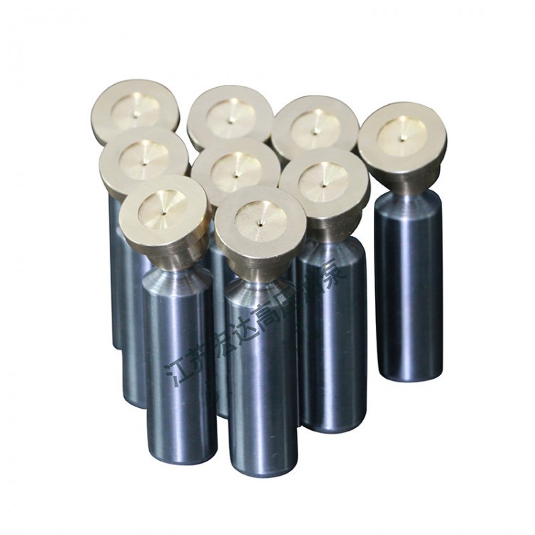
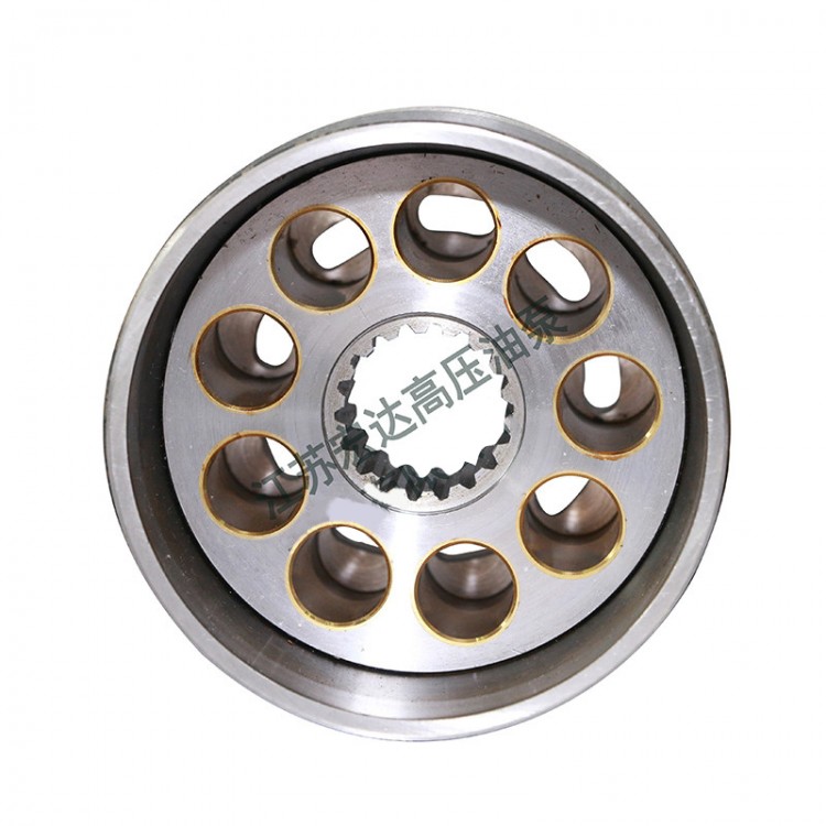
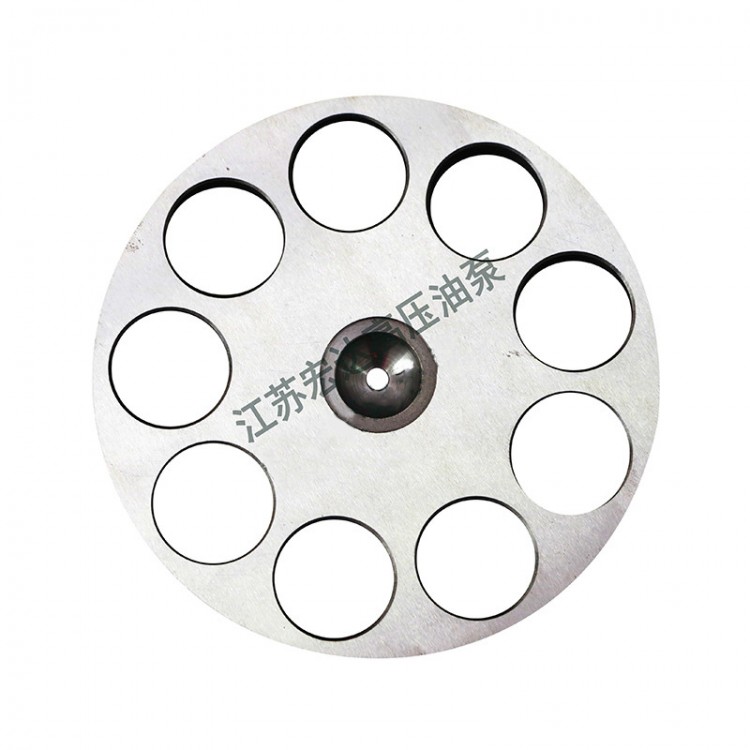
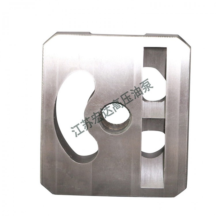
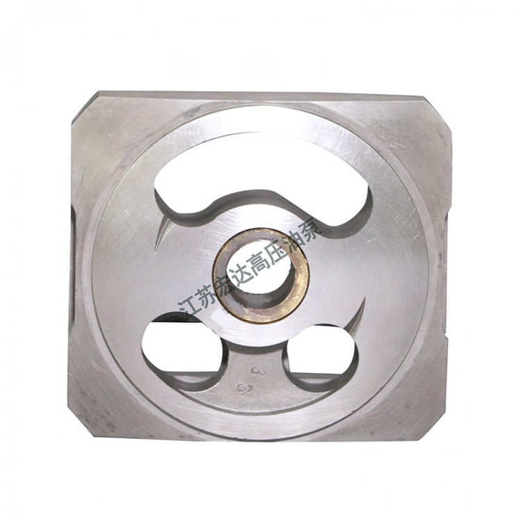
Structural Section
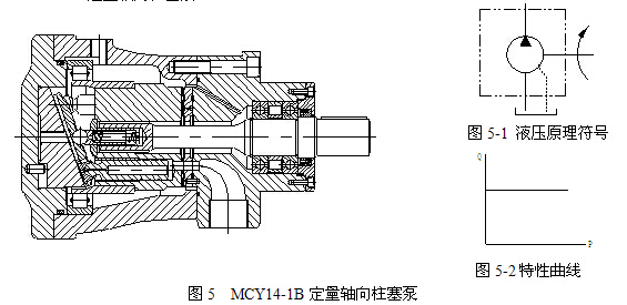
The inclined plate in the metering mechanism is always fixed on the metering end cover, so the stroke of the plunger cannot be changed, making its flow rate fixed.
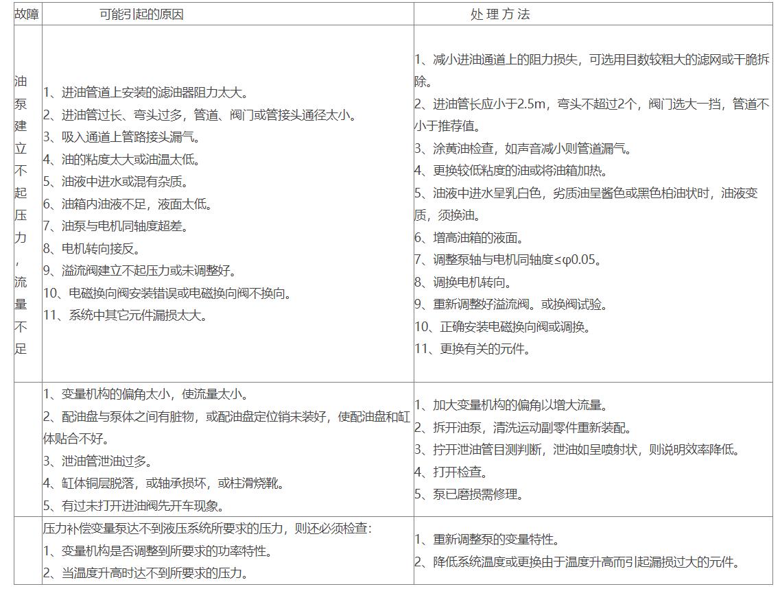
Fault Handling
Operating Principle
Axial piston pumps utilize a distribution plate for oil distribution, featuring a cylinder body rotation and an adjustable swashplate design for variable flow. These pumps are designed with a hydraulic static balance oil film thickness, ensuring the cylinder body operates under pure liquid friction with the distribution plate and the sliding shoe with the variable head. They offer advantages such as simple structure, compact size, low noise, high efficiency, long lifespan, and self-priming capability.
The CY14-1B series pumps are axial plunger pumps that utilize cylinder rotation and variable heads (tilting disks) for variable displacement. Thanks to the design of hydraulic static balance oil film thickness between the sliding shoe and variable head, as well as between the oil distribution plate and cylinder, these two pairs of moving surfaces operate under pure liquid friction. This eliminates the need for heavy thrust bearings, resulting in advantages such as simple structure, compact size, high efficiency, light weight, low noise, long service life, and strong self-priming capability. They are suitable for hydraulic equipment in forging machinery, machine tools, ships, aviation, metallurgical machinery, plastic machinery, construction machinery, and mining equipment.
Power Calculation
N = QP / (60η) (Kw) Actual motor power used
Q—Flow Rate L/min (Actual Flow Rate)
P - Pressure (Actual operating pressure) MPa
η - Total Efficiency Range: 0.85
Users can calculate the motor based on the actual load and select it according to the formula listed above.
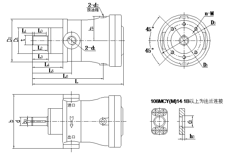
Appearance dimensions
MCY (M) 14-1B Axial Piston Pump (Illustrated as a clockwise pump; the oil inlet and outlet of the counter-clockwise pump are opposite to those of the clockwise pump)