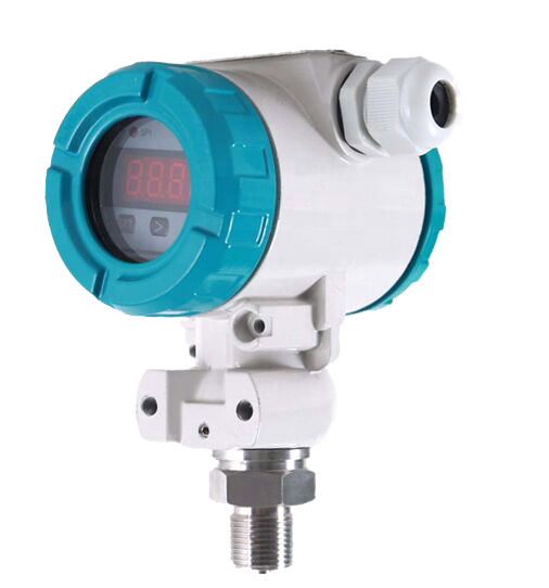


I. Overview:
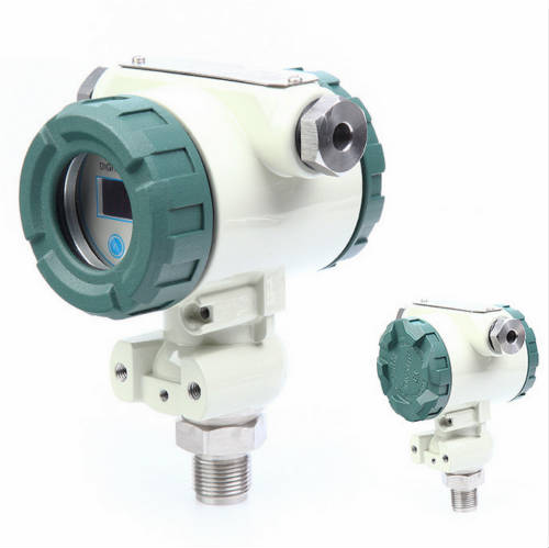
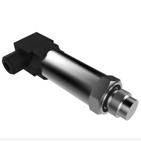
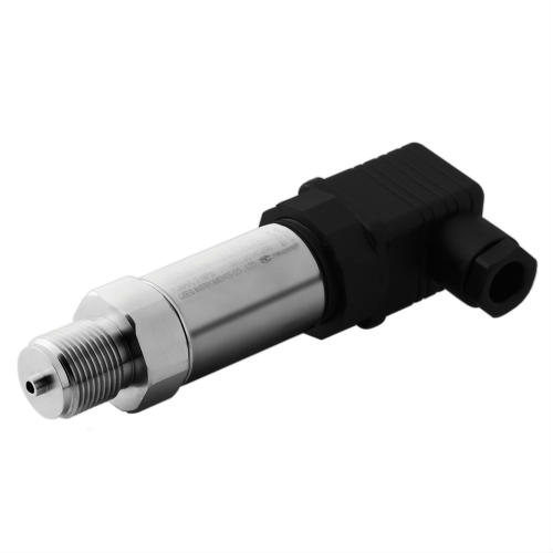
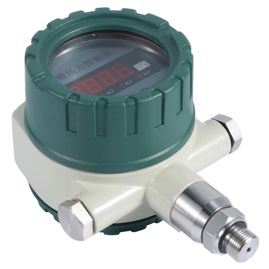
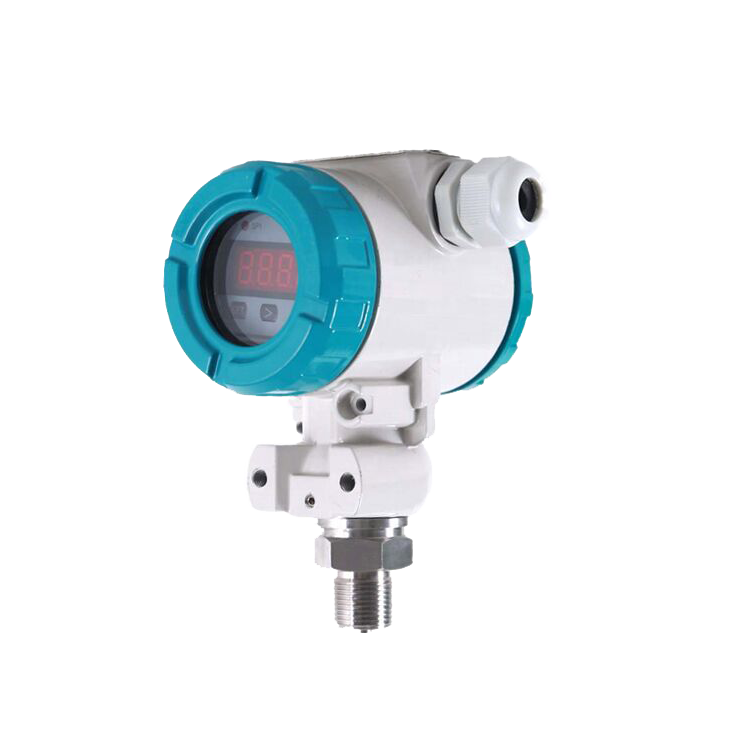
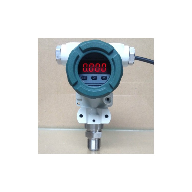
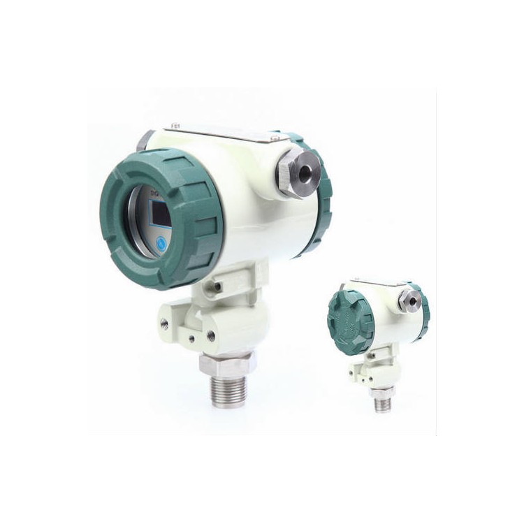
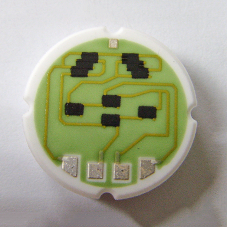
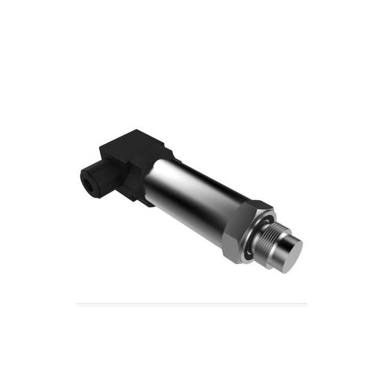
Pressure Transmitter, featuring imported sensor pressure-sensitive elements, temperature compensation via computerized laser trimming, and a unified junction box design. Equipped with dedicated terminal blocks and digital display, it is easy to install, calibrate, and maintain. This series is suitable for various enterprises and institutions in the oil, water conservancy, chemical, metallurgy, power, light industry, scientific research, and environmental protection sectors. It measures fluid pressure and is applicable in all-weather environments and various corrosive fluids.
Product Features
Range -0.1MPa to 0MPa, 0.01MPa to 100MPa
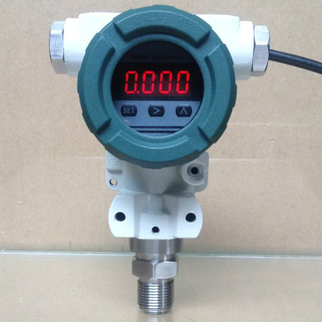
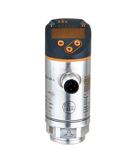
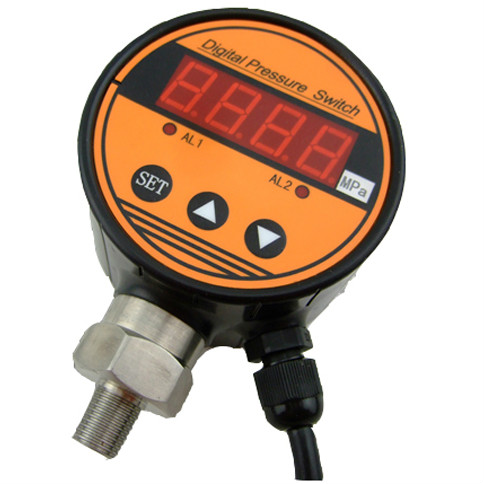
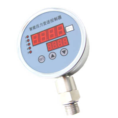
With display, real-time pressure display
Zero-point and full-scale adjustment are convenient.
Reverse polarity protection and current limiting protection
Lightning and pressure shock resistance
High precision, high stability, high reliability
● Application Fields
Industrial Process Control
Hydraulic Measurement
Pressure measurement for various harsh environments
Technical Specifications
| Range | -0.1MPa┅0MPa~0.01 MPa┅100MPa | |||
| Overload | 2 times full scale or 110 MPa (whichever is less) | |||
| Pressure Type | Gauge Pressure, Absolute Pressure, Seal Gauge Pressure | |||
| Power Supply | 12~32V DC | |||
| Output Signal | 4mA to 20mA DC (two-wire system) | |||
| Load Resistance | ≤(U-12)/0.02Ω | |||
| Housing | Explosion-proof cast aluminum housing | |||
| Sensor | 316L Stainless Steel | |||
| Seal ring | Fluororubber | |||
| Ingress Protection (IP) rating | IP65 | |||
| Medium Compatibility | Fluids resistant to corrosion, suitable for 316L stainless steel and fluoroelastomers | |||
| Compensation Temperature | -10℃~80℃ | |||
| Medium Temperature | -30°C to 80°C (LCD Display Type: -20°C to 80°C) | |||
| Storage Temperature | -40°C to 125°C (LCD Display Type: -20°C to 80°C) | |||
| Accuracy | ≤±0.1%FS() | ≤ ±0.25% FS (typical) | ≤±0.5%FS() | |
| Zero-point temperature coefficient | ±0.03%FS/℃ (≤100kPa) | ±0.02%FS/℃ (>100kPa) | ||
| Fullness temperature coefficient | ±0.03%FS/℃ (≤100kPa) | ±0.02%FS/℃ (>100kPa) | ||
| Long-term stability | ±0.2% FS/year () | |||

Electrical wiring


Signal terminals are located within a separate compartment of the electrical box. The cover on the wiring side can be unscrewed for wiring. Power is supplied to the transmitter via the signal wires, eliminating the need for additional wiring. The cover on the wiring side can be unscrewed during wiring. Power is supplied to the transmitter via the signal wires, without the need for extra connections.
The signal line can be a twisted pair. In environments with severe electromagnetic interference, it is recommended to use shielded wire and properly ground it. Do not run the signal line together with other power lines through metal conduits or in the same cable tray, and avoid passing it near high-voltage equipment.
The wiring holes on the transmitter's electrical housing should be sealed or plugged (with sealant) to prevent moisture accumulation inside the housing. If the wiring holes are not sealed, when installing the transmitter, the holes should face downward to allow liquid drainage. Signal cables can also be left unconnected or grounded at any point in the signal circuit, and the transmitter housing can be grounded or ungrounded.
Since the transmitter is grounded through capacitive coupling, a megohmmeter with a voltage not exceeding 100V should not be used when checking insulation resistance. The circuit inspection should be conducted with a voltage not greater than 45V.
Instrument button reset
Under measurement conditions, the instrument is at zero but shows a non-zero reading, indicating zero-point drift. First, hold down the > key, then press the SET key, and hold both for 5 seconds until four dashes appear, displaying '0'. Release the buttons; this is now the zero-point calibration state.
Note: Transmitters are factory-set and generally do not require customer adjustment.
Important Notes
Please connect the wires according to the diagram. If connected reversely, due to the internal protective measures of the transmitter, no signal will be output. The transmitter can operate as soon as it is powered on, but the output signal is more stable and reliable after preheating for 30 minutes. This transmitter is suitable for use in media that do not erode silicon and stainless steel (except for special corrosion-resistant types). The pressure that the measured system can exhibit must not exceed the rated overload value. The back pressure port of the transmitter must not be directly connected to conductive or corrosive liquids or gases, and the gas outlet of the liquid level sealed gas cable must not be blocked. It is strictly prohibited to insert anything sharp and hard into the pressure output port, and the diaphragm of a level membrane-type transmitter cannot be bumped with hands or any other object. This product is a precision primary measuring instrument and must not be dropped, forcefully clamped, disassembled, or pierced with sharp metal tools. The instrument should be installed in a well-ventilated, dry, non-corrosive, and shaded location as much as possible. If the on-site environment is harsh, appropriate measures should be taken to protect the instrument. In case of abnormal output, shut down and inspect. If the issue is due to product quality, return the instrument along with the warranty card and instruction manual for repair and exchange at the factory.
Do not disassemble the instrument circuit board or alter any other equipment by non-professionals.