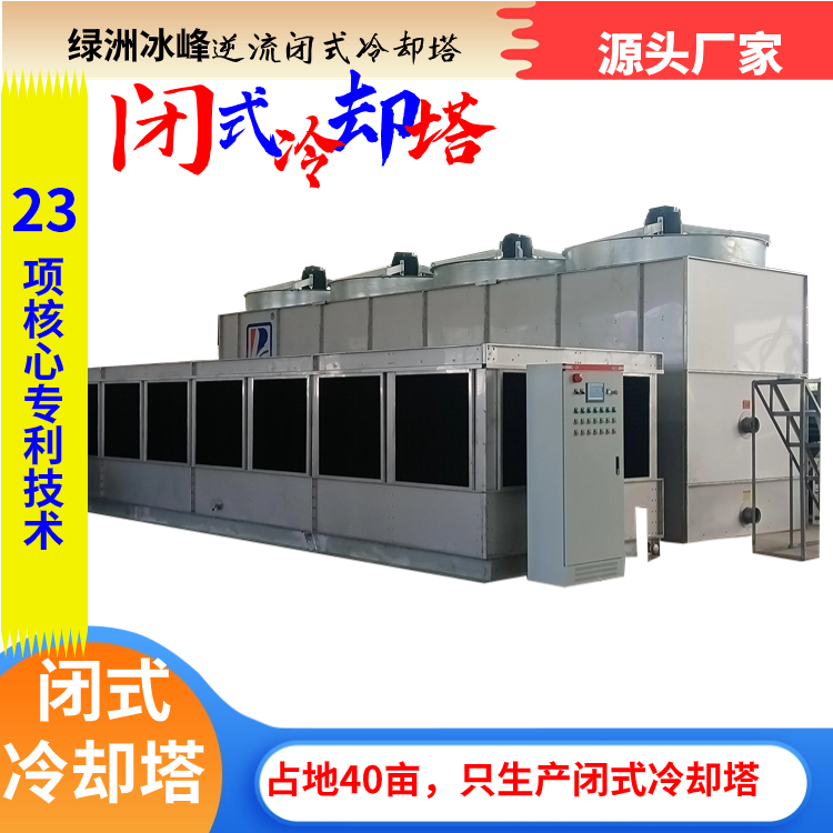


Counter-Flow Closed Circuit Cooling Tower
I. Overview
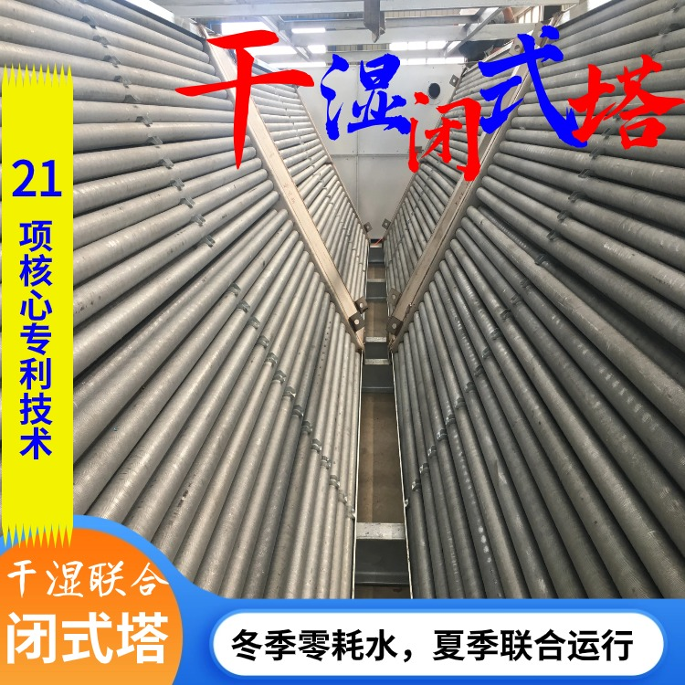
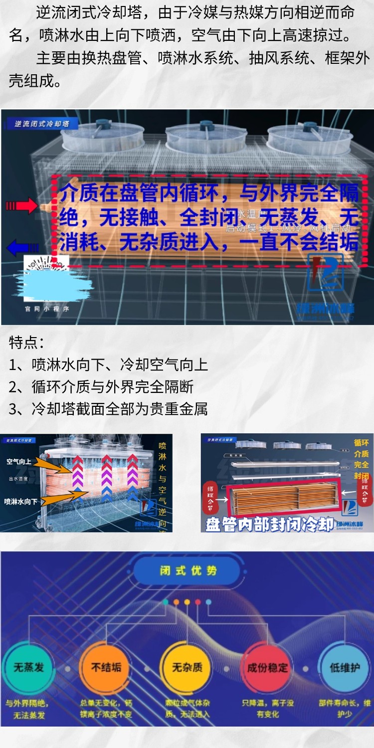
Counterflow closed cooling tower, named due to the opposite flow direction of the coolant and heat medium, with spray water flowing from top to bottom and air passing swiftly from bottom to top.
Primarily composed of heat exchanger coils, spray water system, exhaust system, and framework shell.

II. Process Workflow
The spray pump draws water from the water tank, pumps it to the top of the heat exchanger coils, where it is sprayed uniformly in an umbrella-like pattern over the exterior surface of the pipes, forming a thin water film. A portion of this water absorbs heat from the cooled medium inside the pipes, turning from liquid to vapor. The heat is carried away by the evaporation, while the cooled medium within the pipes is either cooled further or condensed back into a liquid state. The water that does not evaporate falls back into the spray water tank.
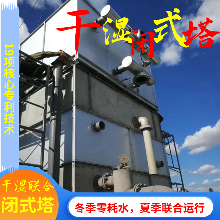
Drafting System: The top fan of the tower is an intake type, drawing air from inside the tower and exhausting it outside. Cold and dry air outside the tower is filtered through the inlet grille and enters the tower. It flows upwards from the bottom of the heat exchange coil, carrying away the evaporated water vapor, increasing the humidity and temperature of the air, which is then exhausted outside by the fan.
In the spray trough, a float valve is installed. When the water level is low, it automatically replenishes the supply to maintain a constant water level in the trough.
Electrical control, online monitoring of the cooled medium's outlet temperature, feeding back to the data processing center, automatically controlling the spray pump and fan operation based on the cooled medium temperature, to achieve energy-saving goals.

III. Principle of Counter-Current Closed Circuit Cooling Tower Operation
1. Internal Recirculation: Recirculated water, after being heated and exchanged with the heat source equipment, enters the air-cooled condenser for inter-wall heat exchange. The cooled recirculated water is then pumped back to the heat source equipment.
2. External Loop: The spray water is transported from the trough to the spray system, where it sprays out and contacts the surface cooler for evaporation and heat exchange. The humid steam is exhausted through the fan, and the non-vaporized spray water falls back into the trough and is then pumped back into the spray system by the pump, to complete another cycle.

Four: Features of Counterflow Closed Circuit Cooling Towers
1. Compact Structure: Compared to crossflow towers, the product structure of this counterflow tower is more compact, offering more surface area for coil heat exchange. It is particularly suitable for cooling projects with smaller temperature differences and higher flow rates.
2. Overall System: Due to the smaller footprint of the cooling tower, combined with the addition of a circulating pump, it can be made into an integrated unit for easy mobility.
3. Application Range: Due to its compact tower, it can be placed in a workshop, making it particularly suitable for medium-frequency power supply cooling and mechanical water jacket cooling. It is especially applicable to projects with smaller temperature differences, such as the cooling of a group of water source heat pump units.
V. Our Advantages
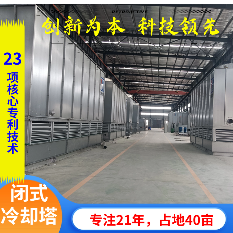
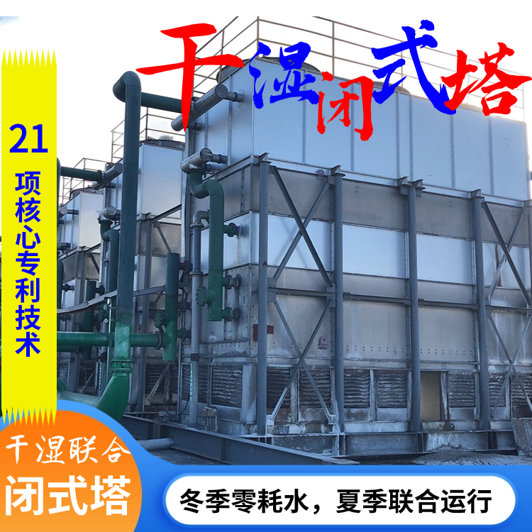
Focused for 21 years, our dedication has made us experts, with rich experience and superior quality.
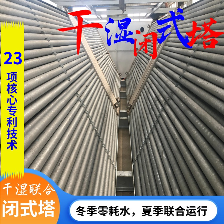
23 patents, backed by patents, reliable technology, excellent performance, stable operation
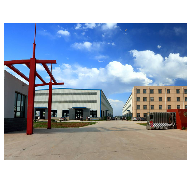
40 acres of land, robust strength, powerful backing, long-term partnership, worry-free after-sales support