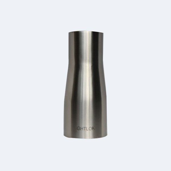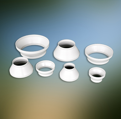


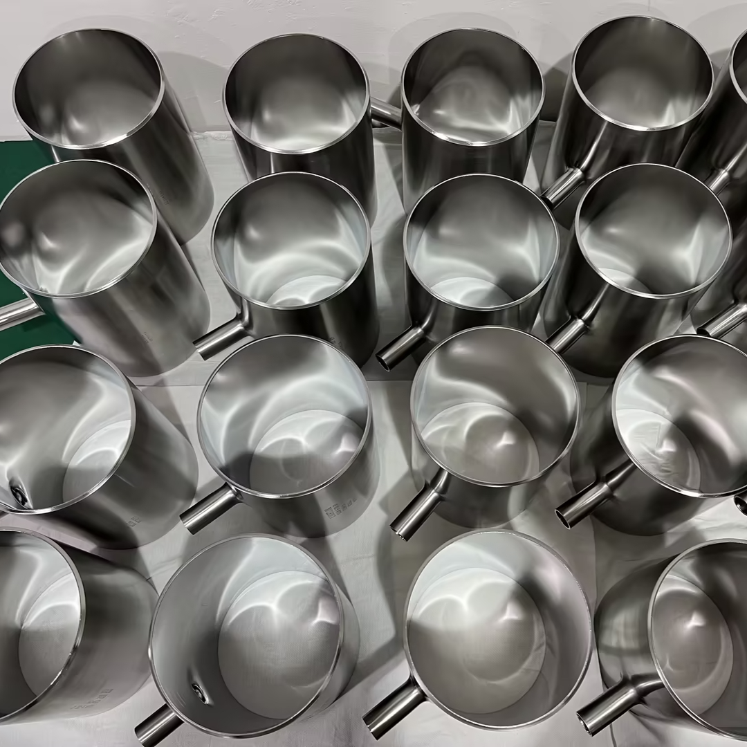


Our pressure flow rainwater gutters (siphon rainwater gutters) are made from stainless steel stamping for the base. The pressure ring and the deflector are cast from hard aluminum alloy and zinc alloy. They feature corrosion resistance and extrusion resistance.
The stainless steel siphon rain collector is completely different from a gravity drainage system. The rain collector typically consists of a rain collector, rain suspended pipe, rain vertical pipe, and rain buried pipe. However, when the rain collects in the gutter to a certain height, the siphon rain collector forms a siphon effect, preventing air from entering until it is completely sealed. This creates a vacuum within the siphon rain pipe, allowing the entire siphon drainage system to operate. The siphon rain collector significantly reduces the depth of water accumulation in the gutter, minimizing the roof's rain load.
The use of stainless steel and alloys in the siphon rain head greatly enhances its lifespan. Rust on the surface of the siphon rain head can affect its functionality.
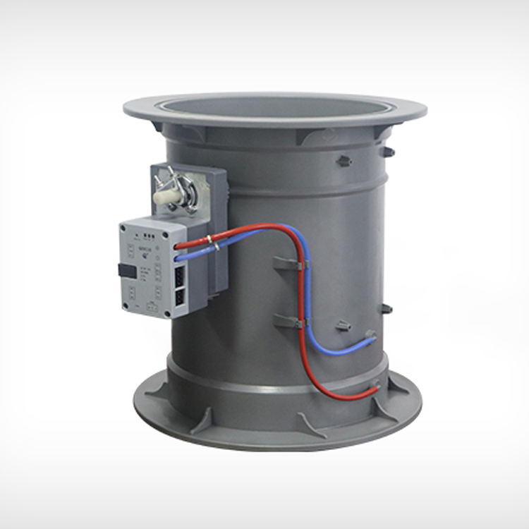
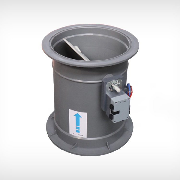
The working principle of the pressure flow roof rainwater drainage system consists of pressurized flow rainwater gutters, rainwater suspended pipes, rainwater vertical pipes, buried pipes, and rainwater outfall pipes. The pressurized flow rainwater gutters have excellent straightening functions, preventing air from seeping in during the designed rainfall intensity. During the rainfall process, the rainwater gutters act like a small, stable water surface pool draining from the roof, passing through the internal roof drainage system and exiting via the discharge pipe. The pipes are in a fully filled pressure flow state, and the roof rainwater drainage process is an siphon drainage process.
Technical Advantages of Pressure Flow Roof Rainwater Drainage Systems: During the rainfall process, the roof collects rainwater along the roof slope into gutters. Traditional rainwater drainage involves directing the collected rainwater from the gutters through rainwater traps, downspouts, and discharge pipes to a stormwater inspection chamber, or through rainwater traps, suspended pipes, downspouts, and discharge pipes to a stormwater inspection chamber. Generally, roof drainage systems are categorized as external or internal drainage systems based on the location and direction of the drainage pipes. From a hydraulic perspective, they can be divided into gravity flow roof drainage and pressure flow roof drainage systems. The latter emphasizes the pressurized condition within the roof drainage system under the design rainfall intensity. Different roof rainwater drainage systems adopt various design calculation methods based on the analysis of their flow states. Traditional roof rainwater drainage systems are designed based on gravity flow, using gravity-type rainwater traps, which result in free weir flow, with the rainwater seeping into the air and forming a water-air mixture, leading to a design flow rate that is smaller than expected. Suspended pipes calculated based on gravity flow require a fill ratio not exceeding 0.8 and a slope greater than 5, necessitating larger pipe diameters and gradients. To ensure the proper operation of rainwater traps connected to the same suspended pipe, it is limited to no more than 4 traps, which increases the number of downspouts. The gravity flow roof rainwater drainage system, due to its hydraulic characteristics, leads to a large number of downspouts, large pipe diameters, and limited drainage capacity, which is more pronounced in large factory and building roof rainwater drainage systems. The pressure flow roof rainwater drainage system, using pressurized flow rainwater traps, significantly improves drainage capacity. Under hydraulic calculation conditions, the number of rainwater traps connected to suspended pipes is unrestricted, thus reducing the number of downspouts and buried pipes. Suspended pipes do not require slopes, making installation convenient and aesthetically pleasing. The system, when calculated based on pressure flow, can reduce the diameter of selected pipes. With a single system's suspended pipe length reaching up to 150m, the main downspout can be close to the exterior wall, and it may not be necessary to create a pipe shaft or bury pipes within the building. This is particularly suitable for locations within buildings where there are many underground pipes or where it is not advisable to set up a shaft.