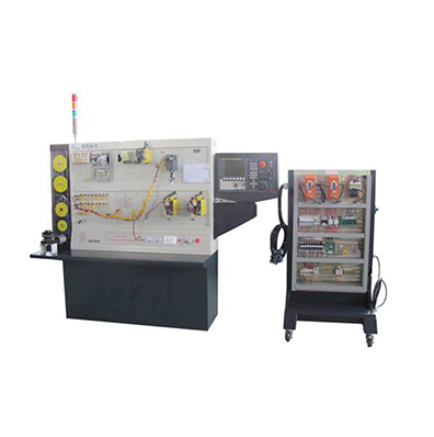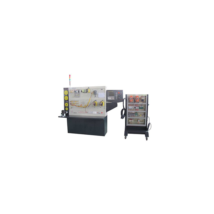


The DS-RTF-E CNC lathe assembly, adjustment, and maintenance training table is equipped with design features for CNC lathe electrical design, installation, wiring, debugging, parameter setting, PLC development, communication, fault diagnosis and repair. It offers educational and training functions for CNC lathe electrical assembly, adjustment, and maintenance.
The training bench is composed of a CNC system, an electric control debugging box, a motor demonstration cabinet, and a movable electrical cabinet.
The electrical control debugging box is composed of modules such as spindle variable frequency, AC servo drive, tool holder control, input/output (I/O), strong electric control, and power supply. Each major component of the CNC lathe's electrical control system is decomposed and displayed on the electrical control debugging box, with all signals capable of being displayed and measured; it can be self-wired and debugged; the fault setting module can set up to 32 fault points, with faults that can be set openly (for training purposes) and secretly (for assessment purposes), and the number of faults can be displayed.
The motor demonstration cabinet displays the AC servo feed drive motor for X and Y axes, spindle motor, and encoder. The feed axis can achieve zero return and feed amount display functions. The spindle motor is controlled by a variable frequency drive to achieve stepless speed change, connected to the encoder via a toothed belt. The industrial four-position electric lathe carriage performs actions such as lifting, positioning, lowering, and locking. All exposed rotating parts are equipped with complete protective devices.
A mobile electrical cabinet for CNC machine installation and debugging, independent of the training table, with a control cabinet identical to industrial CNC machine control cabinets. It allows for practical training in circuit design, electrical component installation, wiring, and debugging. The electrical board is interchangeable, facilitating group-based practical skill training for students. The electrical board is equipped with simulated drivers and inverters, providing a more realistic training experience and protective devices to reduce costs.
1. Lab Training Content
● CNC System Functions, Structure, Installation, Parameter Settings, and Tuning
● CNC Machine Tool Alarm Recognition, Fault Diagnosis, and Repair
● CNC system data backup, communication with computer
●Servo Motor Drive Wiring, Tuning, and Dynamic Characteristics
● Main shaft motor inverter wiring, parameter setting, and tuning
● Principle of control, wiring, and debugging for a four-station tool holder
● Principle and Application of Hall Elements and Proximity Sensors
Encoder (Circular Encoder) Actual Applications and Thread Machining Experiment
● Experimental and debugging of semi-closed-loop control
PLC commands, programming, wiring, and application in CNC machine tools
● Definition, setup, and debugging of input/output interfaces
● Principles and Applications of CNC Machine Tool Peripheral Control Circuit
● Principles, Performance, and Wiring of Low-Voltage Electrical Components
Ball screw pitch, transmission ratio, and other parameter settings
● Reverse Clearance Compensation, Lead Screw Pitch Error Compensation Experiment
● Programming and interpolation motion experiments for CNC machine tools
CAD/CAM-based DNC Application
● Programming and simulation of CNC machine tools
● Perform wiring and debugging training for machine tool electrical cabinets