


Product Advantages:
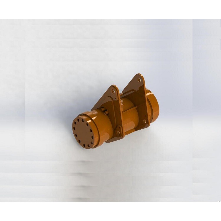
The product design is compact; it's all about the millimeter, less or more.
Multiple installation options, simplifying the structure of rotational movement, making your design more compact.
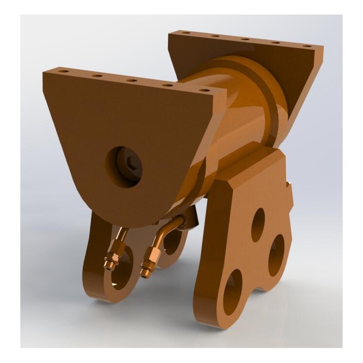
This product can withstand high axial and radial loads.
Optional rotation angles from 90° to 360° to meet your diverse needs.
The balance valve serves as a protective mechanism against mechanical damage when subjected to excessive reverse load.
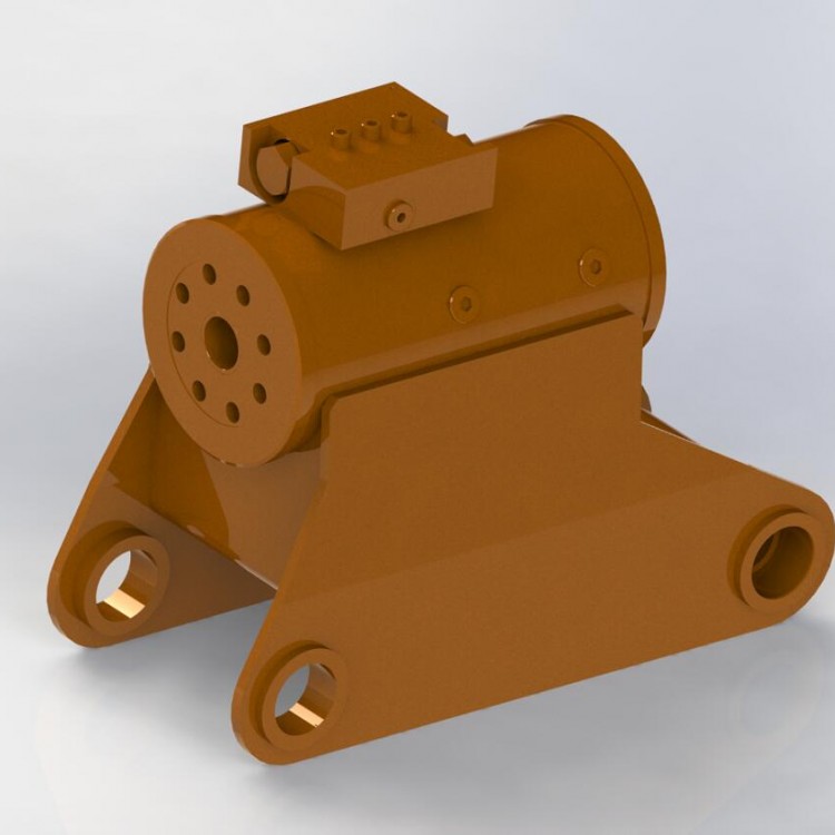
The product is meticulously crafted with zero internal leakage.
The balance valve allows the product to stop at a fixed position in its stroke and maintain torque.
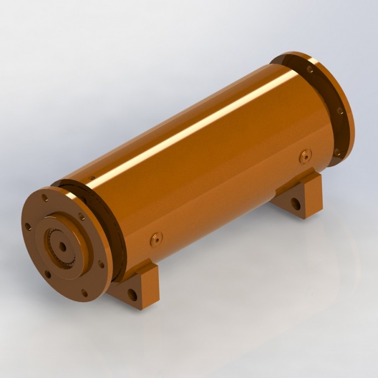
The helical swing cylinder is currently a product with a high torque output per unit volume.
A swing hydraulic cylinder is a compact component that, in a small space, utilizes hydraulics to generate a high torque. It features a composite helical gear structure, allowing the entire swing hydraulic cylinder to produce a greater torque within a smaller space. Despite the high power, they can still be easily controlled. The swing hydraulic cylinder has been successfully applied in almost all fields requiring limited rotational motion and high torque.

The helical oscillating cylinder is a structure that converts linear motion into rotational motion through the relative movement of the spiral pair, available in both single and double spiral configurations.
For example, with a double helix structure:

Assuming the housing ① is stationary. As hydraulic oil passes through the P2 port and acts on the piston sleeve ③, the piston sleeve ③ will move axially to the right. This is because the spiral gears mesh with the piston sleeve ③ and shaft ②, causing them to rotate simultaneously. Shaft ② will rotate clockwise as indicated by the arrow in the diagram. Note that shaft ② has no axial movement, while the piston sleeve ③ rotates and moves axially. Housing ① is fixed to the gear ring, with no relative motion.
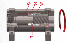
Assuming the housing ① is stationary. As hydraulic oil passes through the P1 port and acts on the piston sleeve ③, the piston sleeve ③ will move axially to the left. This is because the spiral gears mesh with the piston sleeve ③ and shaft ②, causing them to rotate simultaneously. The shaft ② will rotate counterclockwise as indicated by the arrows in the diagram. Note that shaft ② has no axial movement, while the piston sleeve ③ rotates and moves axially. The housing ① is fixed to the gear ring and there is no relative motion between them.


