


Product Details
Model Overview
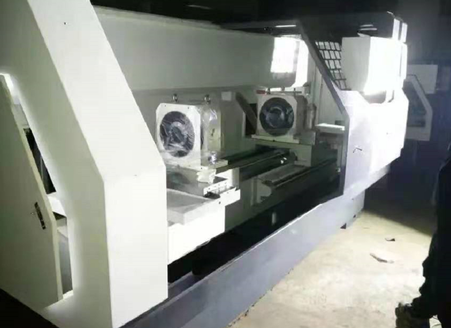
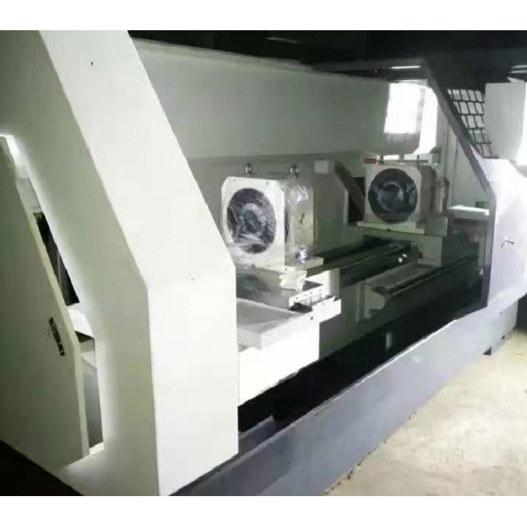
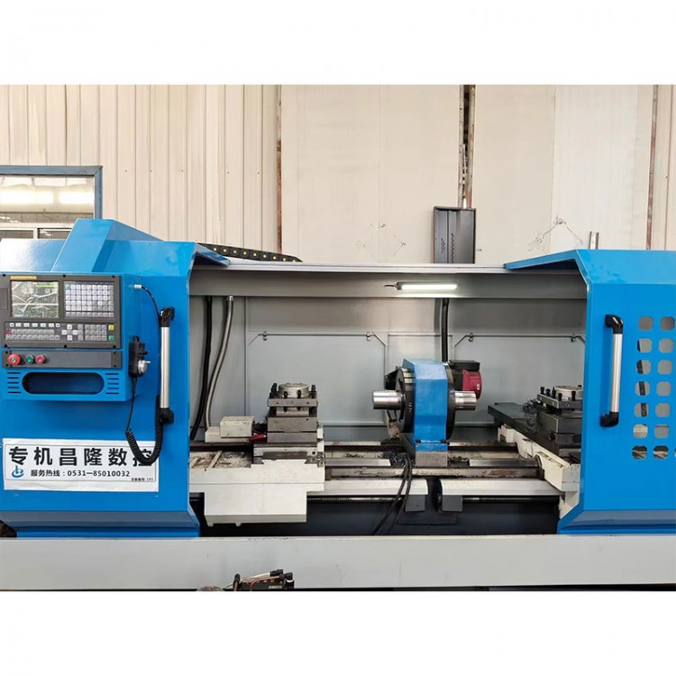
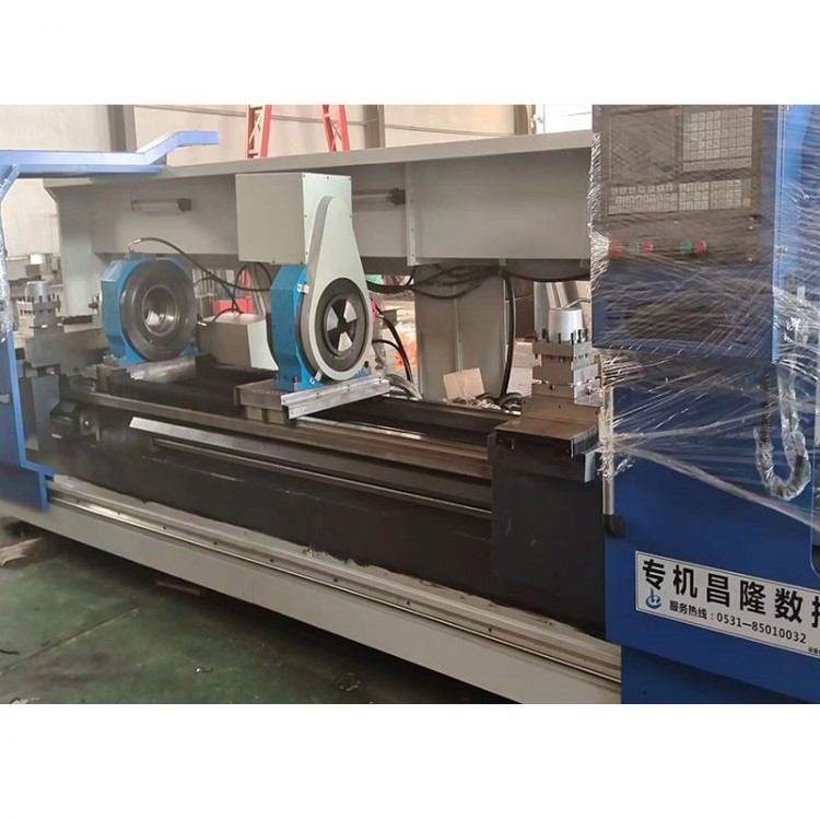
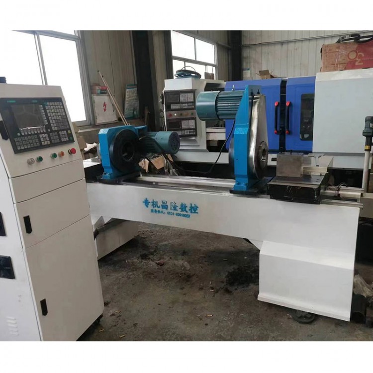
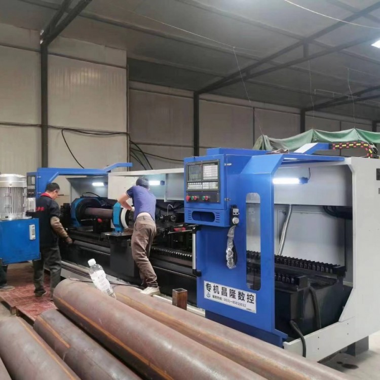
Machine Tool Name: CNC Double-Head Lathe
2. Machine Tool Model: CKS120-2000
3. Machine Tool External Dimensions: Approximately 45001800x1800 (inclusive of protective cover)
4. Machine Tool Weight: Approximately 3800KG
5. Total Power of Machine Tools: Approx. 20KW
Motion control and functional realization
1. Motion Control
1). Machine tool feed movement is controlled by two Beijing Kaindi CNC numerical control systems, each controlling a set of slides. Servo motors drive the screws to achieve bi-directional feeding.
2). The main shaft is driven by a servo main shaft motor, allowing the speed to be adjusted at will within the speed range (CNC programmed control).
3). The workpiece clamping action is achieved by hydraulics.
4). Parts loading and unloading are manually handled.
2. Functional Implementation
Main functional modules of machine tools are categorized into several major types:
Control System: Automates machine tool processing through CNC system programming. One system controls one side plate. It completes processes like workpiece turning through tool changing and CNC interpolation. The system is non-interfering in G-code programming. It has logical relationships during start-up and shutdown in automatic operation. The system has a master-slave relationship, with the master system controlling the spindle start/stop, speed setting, workpiece clamping, cooling switch, and corresponding plate interpolation control functions. The slave system only controls the corresponding plate interpolation action.
2. Bed Frame: Serves as the support for installing various components. The bed frame material is HT300, which undergoes annealing treatment after casting and stress relief through harmonic vibration aging.
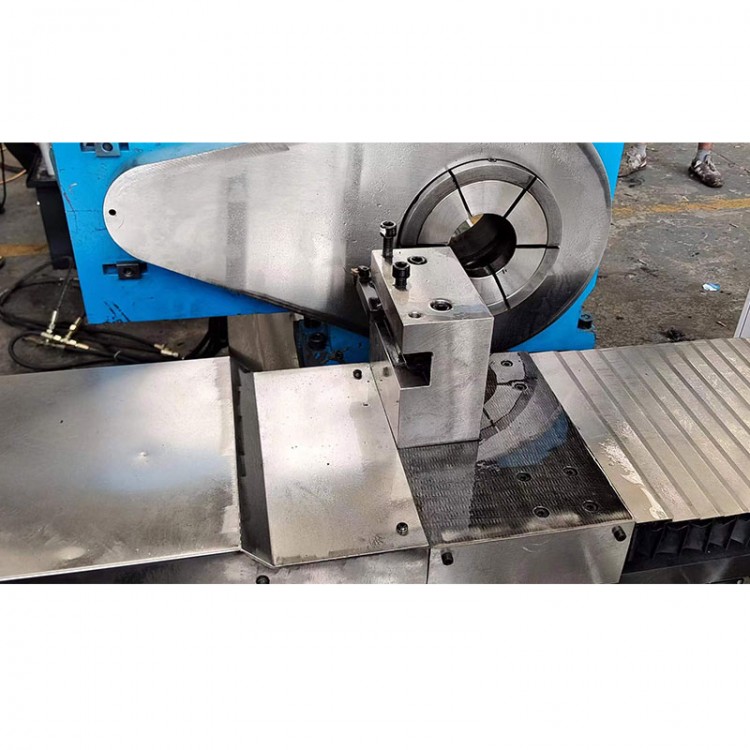
3. Spindle and Spindle Drive: The machine tool spindle is a hydraulic chuck twin-spindle main spindle. The maximum designed speed is 2000 rpm. The spindle drive is a 5.5KW dedicated servo motor, which is synchronized with the spindle at a 1:1 ratio via a steel wire synchronous belt. CNC control allows for setting different speeds.
4. Feeding Drive: This machine converts the rotational motion of a servo motor into linear motion of the screw, driving the platform to achieve linear feeding during the machining process. The machine tool servo motor is controlled by KND Company for bidirectional feeding. The lead screw uses precision ball screw pairs. The main body of the plate is HT300 cast iron, heat treated and harmonic vibration aged. The quick-moving speed of the plate is 10 meters/min. The minimum feed amount of the plate is 0.001mm.
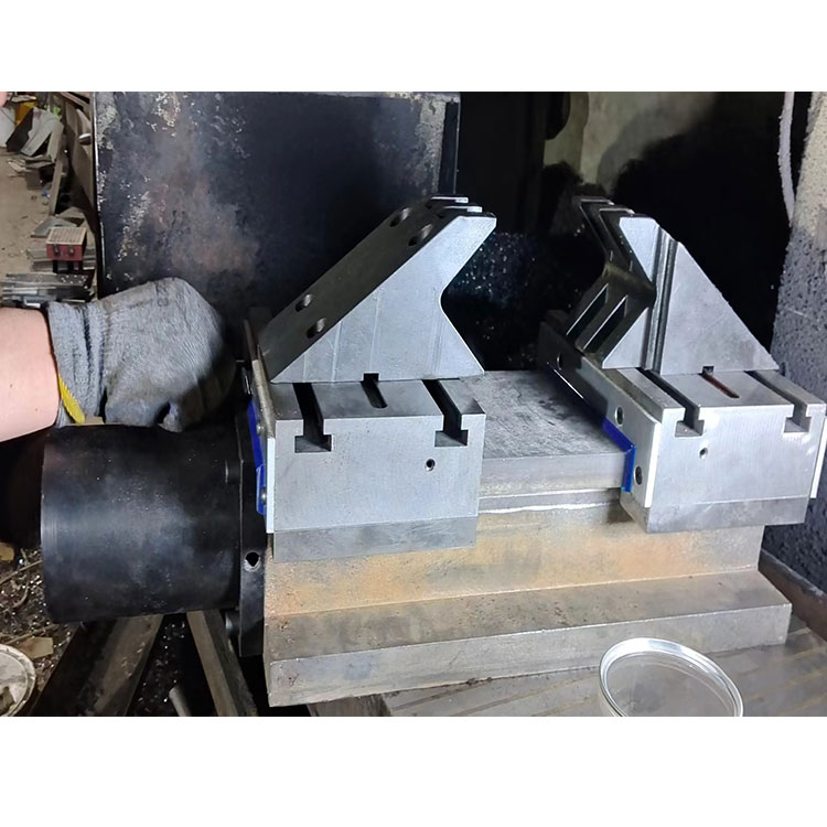
5. Workpiece Clamping: The workpiece is held by hydraulic clamping. Different workpieces require different chuck selection.
6. Centralized Lubrication System: The machine tool is equipped with an automatic centralized lubrication system. The system lubricates automatically and features a low-fluid alarm device.
7. The processing area is equipped with waterproof lighting fixtures.
8. Tool Installation: The four-position electric tool holder is extremely easy to adjust, saving auxiliary time. Particularly effective in the internal hole processing, it achieves a great effect on the surface finish of the workpiece.
9. Standard equipment includes an automatic cooling system for machine tools.
10. The system comes with built-in data backup and network connection interfaces.
11. Cutting Tools: Blade shafts and blades to be provided by Party A.
12. Machine Tool Protection: The machine tool sheet metal features a semi-enclosed waterproof structure, with a folding protective hood mounted on the support plate.
3. Establish safety warning signs
3.1 Safety warning symbols for the operator
1). Recommended Personal Protective Equipment
2). Emergency Shutdown Procedure
3). Chemical Safety and Warnings
3.2 Safety warning signs for maintenance personnel, including required maintenance procedures when the equipment is not de-energized, which includes but is not limited to isolation warnings, signage postings:
1). Describe and locate each de-energized and/or energized device.
2). Actions taken for each de-energized and/or energized device.
3). Method for determining whether the electrical power is disconnected or the stored electrical energy is in a released or locked state.
4). Procedure for safely energizing equipment for testing and debugging.
5). Procedure for safely restoring the equipment to operational status.
4. Safety protection, prevention, and equipment control
1). Devices for actions such as belts, connectors, rotating shafts, drive chains, and clamping positions are fully enclosed.
2). Employees are strictly prohibited from accidentally entering the equipment workspace.
3). The emergency stop button is a red mushroom-shaped button with a protective cover to prevent accidental activation.
5. Electrical Components
1). The equipment features a locking mechanism, which can only be activated when specifically required in the "open" position. Otherwise, the safety device remains in the "open" state, and the interlock cannot be manually operated.
2). Electric switches with locking function can be easily located from the control panel position.
Machine Tool Processing Range and Precision
1. Range of Processing
1). Hold outer diameter: Φ20--121mm.
2). Clamping Length: 500-2000mm.
4). The machine tool can perform simultaneous operations such as facing both ends, setting total length, chamfering, turning external and internal bores, etc.
2. Processing Accuracy
1). Hole Depth: ± 0.01mm.
2). Outer diameter: ±0.01mm, coaxiality of both ends' outer diameters and inner holes: < Φ0.015mm.
3). Turning Surface Roughness: Steel parts Ra≤1.6.
Axial dimension tolerance: ±0.015mm.
Machine Tool Configuration List
1. Technical Documentation
| Serial Number | Content | Unit | Quantity | Notes |
1 | Machine Tool Operating Manual | Booklet | 1 | |
2 | Certificate of Compliance | Booklet | 1 | |
3 | Packing List | Booklet | 1 | |
4 | Warranty Card | Booklet | 1 | |
5 | User Manual for the System | Book | 1 |
2. Random Attachments
Serial Number | Content | Specs | Unit | Quantity | Note |
1 | Foot pad iron | Φ160 | Only | 8 | |
2 | Hexagon Wrench | Group | 1 |
3. Configuration Sheet
Serial Number | Name | Specs | Origin | Note |
1 | Machine Tool Model | CKS120-2000 | Changlong | Flat bed frame |
2 | System | KND | Beijing | Or Optional |
3 | Servo main motor | 5.5KW | Domestic Quality | |
4 | Servo Motor | KND | Beijing | |
5 | Driver | KND | Beijing | |
6 | Claw | 1 Set (Standard Configuration) | Chang Long | Cost price of 800 for two sets included |
7 | Hand-held pulse reader | KND | Beijing | |
8 | Screw Thread | 4010/2505 | Han River | |
9 | Electrical Components | Electrical Components | Chint | |
10 | Rack style | Four-position electric knife holder | Changzhou | Optional blade selection |
11 | Hydraulic Station | 8th Road | Domestic Quality | |
12 | Lubricant | Automatic Lubrication Pump | Nanjing | |
20 | Spindle Speed Range | 50-2000r/min | ||
21 | X-axis maximum travel | 300mm | ||
22 | Z-axis maximum travel | Over 3000mm | ||
23 | X-axis fastest moving speed | 10000mm/min | ||
24 | Z-axis maximum moving speed | 10000mm/min | ||
25 | X-axis repeat positioning accuracy | ≤0.004mm | ||
26 | Z-axis repeat positioning accuracy | ≤0.006mm | ||
27 | Machine Tool Dimensions: Length x Width x Height | 4500×1800×1800mm | ||
28 | Machine Tool Net Weight | Approximately 3,800 kg |
Equipment Acceptance
1. Pre-acceptance Standards and Requirements:
During the pre-inspection period, Party B provides the following conveniences: local transportation, working lunch, receiving and sending faxes and emails, and safe working conditions.
2). Party A provides samples, which will be inspected according to Party A's drawings with the precision. The inspection will be conducted at Party B's factory (with the part number sample as the standard for inspection).
3). The cooling fluid, hydraulic oil, lubricating oil, and other media required for pre-inspection are provided by Party B.
4). The special gauges or instruments for checking the accuracy of the testing equipment used in pre-acceptance of the equipment are provided by Party A.
5). Process continuously at the specified rhythm, ensuring that the processed parts meet the requirements of the drawings and technical agreement.
6). Acceptance Standard: Part 1 of GB/T 16462.1-2007 - Inspection Conditions for Numerical Control Lathes and Turning Centers: Geometric Accuracy Inspection of Horizontal Machining Centers. Part 1 of GB 5226.1-2008 - General Technical Conditions for Electrical Safety of Machinery and Electrical Equipment.
2. Final Inspection
1). Installation and debugging, as well as final acceptance, will be conducted at the buyer's factory. Upon receiving the equipment, the buyer should promptly notify the after-sales service to assist with installation and debugging, and provide support along with convenient conditions. If installation is not possible due to the buyer's factory site or other issues, the equipment will be deemed to have passed final acceptance after one month of arrival.
2). Verify that all random accessories and technical documents are complete.
3). Party A shall prepare the equipment usage conditions, including power, gas, oil, tools, and other requirements, as well as the ground requirements for equipment usage. Additionally, Party A shall prepare the test pieces and the gauges required for inspection.
4). The equipment runs for 8 hours without failure, and after the static accuracy meets the factory requirements, a trial cut is conducted.
3. Installation and Commissioning
Party B is responsible for equipment installation and debugging. Party A bears full responsibility for the reliability and correctness of the equipment hoisting, positioning, installation, and debugging.
2). Party A provides electricity, water, compressed air, on-site office, and Internet for installation and debugging.
3). The Buyer shall assist the Seller in the installation of the power and medium branch pipeline connections required for the equipment, with the branch materials provided by the Seller.
4. Training:
Party B is responsible for the technical guidance on the installation, debugging, and trial production process of the equipment after it is placed at Party A's site. In conjunction with on-site debugging, Party B provides on-site training and guidance to Party A's operators to ensure they can smoothly and proficiently operate the equipment, maintain and service it, replace new varieties, and troubleshoot routine equipment malfunctions. (Personnel from Party A receiving technical training should have a junior college or higher education level).
After-sales service
1. Warranty Period and Scope
The warranty period for quality assurance is 12 months from the final acceptance; within one year of final acceptance, our company will provide free technical staff training for operation, maintenance, and other technical aspects of the equipment. Ensuring your staff can operate the equipment proficiently and use and maintain our products correctly as per the instructions.
2. The following situations are not covered under our company's warranty.
Therefore, any repair costs incurred will be borne by you: failures of parts, equipment, not produced, modified, or supplied by our company; product failures due to natural disasters or other irresistible factors; our company's products that have been disassembled or modified by the user without our permission; product failures caused by misuse or failure to follow the instructions; service issues due to improper operation or process by the user; product failures beyond the warranty period.
3. Maintenance and repair costs
During the warranty period, free repair and replacement of parts for non-manual damage and malfunctions. For machine tool damage caused by human operation errors, only the cost of replacement parts is charged. Post-warranty service, in addition to the cost of parts, suppliers may charge for labor and travel expenses.
4. Fault受理
1). Our products come with lifetime warranty. To ensure the quality and efficiency of the repair service, please directly contact our maintenance department when the equipment malfunctions. When reporting a repair, please provide your company name, address, phone number, product model and serial number, configuration system model, and the nature of the fault for our timely and accurate service.
2). Respond to notification by phone within 2 hours, provide a response and processing opinion within 4 hours, and arrive at the buyer's site within 24 hours if phone and fax cannot resolve the issue. Responsible for timely troubleshooting, general faults to be resolved within 2 days, and special faults to be repaired within no more than 5 days.
3). Phone Consultation: Free technical support via a dedicated consultation hotline is offered to address any issues users may encounter during the trial of machine tools, promptly providing solutions and operational methods.