


I. System Composition
Xiaobeng Technology's comprehensive optical fiber telephone solution is a highly integrated management system that can exist independently as a phone system or simply replace the costly centralized control platform of a monitoring center (multi-system联动). It is particularly suitable for intensive projects. The system consists of a central management system deployed at the control center and branch stations (node hosts and telephone subunits) installed in the pipeline. The central management system includes an integrated pipeline digital programmable exchange (with access to the monitoring system), an optical fiber telephone access host (with access to wireless AP systems, fire linkage alarm systems, and independent broadcasting systems), a touch screen dispatch console, and software for an integrated pipeline emergency telephone dispatch system.
II. Detailed Function Description
A fiber optic telephone access main unit configured with 2 SC optical ports to form a ring network (up to 4 rings), 8 adaptive LAN ports for networking, with each ring network capable of connecting 1024 telephones. The standard system configuration includes 256IP model extensions, 8-way ring relay (configurable for expansion).
1. Unlimited Inbound and Outbound Calls: The system enables communication between internal nodes' hosts (or backup machines) within the pipeline, as well as between these hosts (or backup machines) and the control center. It also allows direct phone connections to external public network users for each internal node's host (or backup machine), with communication permissions being controllable.
2. Broadcast Function: The management personnel at the control center can use the touch screen on the dispatch console to activate the comprehensive pipeline emergency telephone dispatching system software, to issue voice broadcasts to the auxiliary telephones, convene meetings, and arbitrarily select the controlled scope of the broadcast as needed.
3. Monitoring and Permission Settings: The center can monitor and set permissions for calls on any node host (or backup machine).
4. Fiber Optic Self-Healing: The optical fiber telephone node host and access host form an optical fiber ring network structure, featuring the fiber optic self-healing ring function. The overall system switching and self-repair time is less than 100ms. A single node host failure does not affect the normal operation of other node devices (or sub-machines) and the telephone system.
5. Recording and Playback: The system is capable of recording all calls between the center and external lines, as well as all calls within the tunnels. It also allows for searching and playback of recording logs, with a standard recording duration of 30,000 hours.
6. Each branch (or auxiliary) station can call the dispatch center by dialing or picking up the line directly. The dispatch desk phone at the control center will ring, and the integrated pipeline emergency dispatch system software installed can directly display the caller's phone number, Chinese name, and location, such as Integrated Compartment 01, Section 1, No. 1.
7. Dispatchers can call any internal node host (or backup) within the pipeline from the control center. The call operation simply requires picking up the phone and pressing the corresponding button on the touch-screen dispatching console, automatically establishing a full-duplex conversation.
8. All extension calls are unblocked, and when multiple extensions initiate calls, they automatically queue up. The names and numbers of the queued extensions are displayed. Calls are handled on a first-come, first-served basis. Dispatchers can also choose to answer any queued extension by simply clicking the "Priority" button on the dispatch console and then selecting the extension from the queue to answer.
9. The alarm prompt voice can be recorded into the dispatching system (connected to fire linkage alarm system). When the corresponding switch is activated, the corresponding alarm prompt voice is played. If linked with front-end collection sensors, when a gas detector in a specific area detects a leak, it triggers a switch quantity to the dispatching system. The dispatching system can initiate calls to all local extensions within the area according to a pre-set plan. Upon answering, the corresponding alarm prompt sound is automatically played.
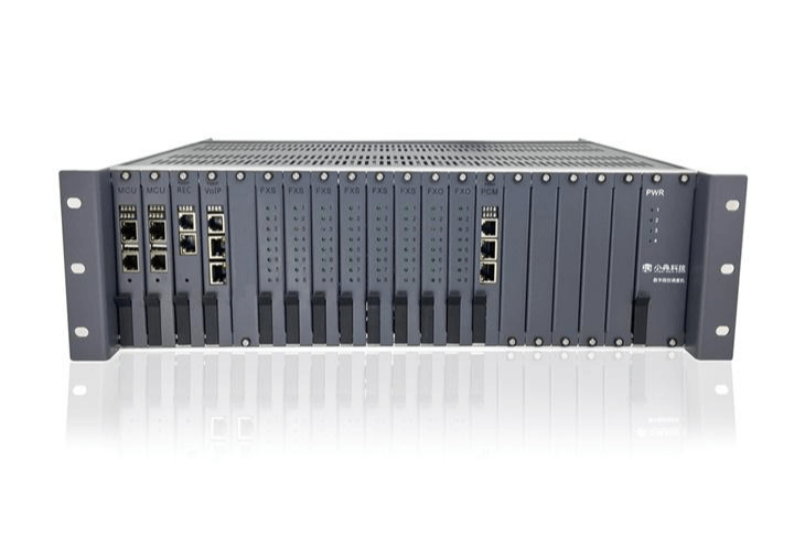
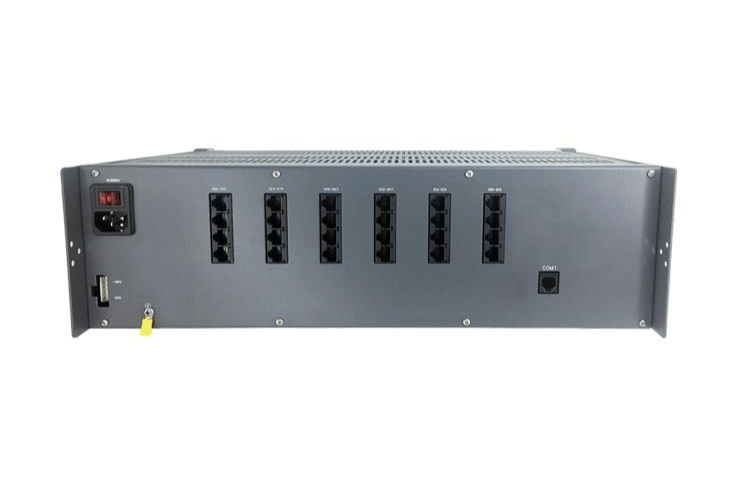
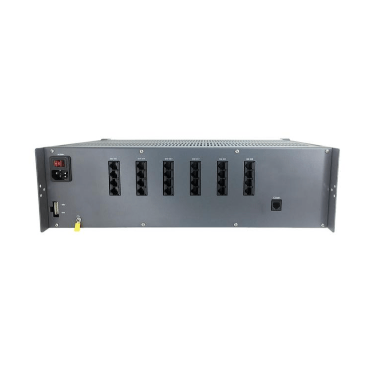
10. The scheduling machine features a card-based design, allowing flexible configuration according to the customer's actual needs, facilitating future expansion and investment protection. It supports IP extension registration, analog user FXS extension, loop-back relay FXO, digital relay E1, recording board REC, IP relay, etc. The common section supports hot backup redundancy design, ensuring uninterrupted call switching during mainboard switching. All cards support hot-plugging, making maintenance convenient.
11. Supports integration with video surveillance systems. Simply add a video server and connect it to an IP camera or a hard disk recorder of a monitoring system. Bind the camera location with the nearest extension, and when the dispatcher clicks on the bound extension on the dispatch console, the live feed from the camera in the area of the extension will pop up directly on the dispatch console, facilitating a more intuitive understanding of the situation for the dispatcher.
12. Supports WIFI mobile access (wireless AP system integration). In projects with installed wireless APs, WIFI mobile phones can be provided for managers, facilitating easy portability and timely communication.
Section 3: Node Host and Secondary Function
Node Host (Fiber Optic Emergency Telephone) Deployment Location: Substation Transformer Bay/Inlet/Exhaust Vent
● Telephone type node host, standard 0-9, star/diamond, redial/flash disconnect dial, supports regular dialing and direct dial via pickup hot line (emergency call)
Texas Instruments VoIP Voice SoC, SIP 2.0 Communication Protocol
● Taiwan REALTEK Fiber Transmission SoC, Ring Network Self-Healing Time <100ms, Throughput Capacity 2Gbps
● Full IP65 protection rating, standard three-proof design, anti-mold/anti-humidity/anti-salt spray, orange ABS glass fiber reinforced body
●SC optical port x2, reserved adaptive RJ45 network port x2, capable of connecting external wireless AP, IP camera
The phone mouth is connected using a dedicated cable, allowing for full concurrent connection of 7/15 telephone subunits.
● Transmission Cables - Single-mode Single-fiber (Single-core) Bi-directional Transmission
● Fiber Wavelength: 1310/1550 NM
● Transmission distance of 20 kilometers (between node hosts), downstream phone substation transmission distance of 1.5 kilometers
● Full load power consumption: 15W, Standby power: 10W
● Power input: AC 220V 50Hz, wide voltage range of 85-264V
Operating Temperature: -30℃ to +60℃
●Operating humidity 10~95%RH (at 30℃)
Waterproof/Blast-proof Telephone Substation (Fiber Optic Emergency Telephone Substation) Deployment Location: Various compartments in pipeline galleries, such as power compartments, integrated compartments, and gas compartments, etc.
● Suitable for environmental temperature range: -30° to +60°
● Suitable environmental noise range: 0 to 60dB (A/C/D models), 0 to 120dB (E/F models)
● Ring Volume: ≥90dB (up to 95dB, at two feet)
● Two appearances: Dial pad/Through cable
Engineered for extreme harsh conditions, suitable for rail transit, highway networks, tunnels, and vessels.
Waterproof and dustproof design, protection class (IP66)
● High-strength reinforced ABS engineering plastic / full aluminum alloy body, total weight over 3KG
LED Night Vision Keypad
● Modular design-based, customizable additional features
Note: The basic model does not require additional power supply. The broadcast model requires additional configuration and an extra 220V power supply connection.
The gas compartment is explosion-proof equipment, while the other compartments are waterproof equipment.
Section 4: Product Introduction
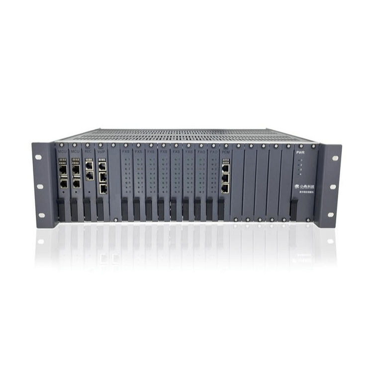
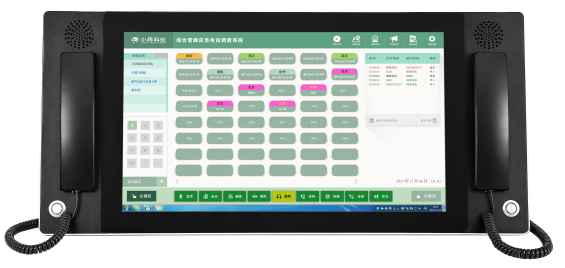
Tunnel Corridor Type Digital Programmed Dispatching Machine

SPC8000-G3 Comprehensive Utility Trench Emergency Phone Dispatch System
The system fully integrates the functions of digital switches and gatekeepers, representing the new generation of programmed dispatching systems, offering ultra-powerful external line dispatching and interconnection capabilities.
Utilizing ultra-large scale communication dedicated chips, dedicated DSP digital signal processing chips, FPGA programmable logic chips, and more, the system ensures low power consumption, high efficiency, long lifespan, and high reliability; all common units are fully hot-backup capable with seamless switching; all unit boards support hot-plugging; system hardware monitoring functions, automatic isolation upon unavailability or failure; critical relay routes can operate in a primary-backup mode; the system employs three-tier lightning protection and has passed the K20 lightning resistance test, fully meeting the special requirements of heavy lightning areas.
Motherboard, secondary power supply hot backup;
Hot-plugging, mixed plugging;
Multi-priority force insertion, force removal, group force insertion, group force removal
Dispatch and Monitoring Function
200 conference sets (mixed landline and VoIP)
In-line and off-line call waiting
Advanced full-channel digital recording system, hard disk file management system, and scalability.
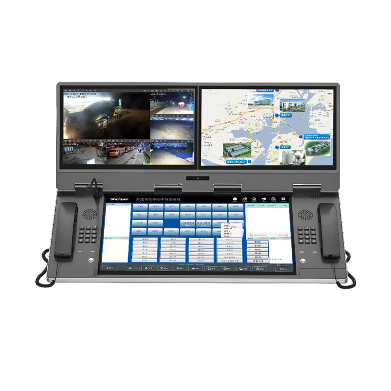
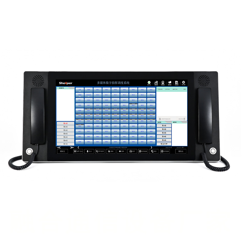
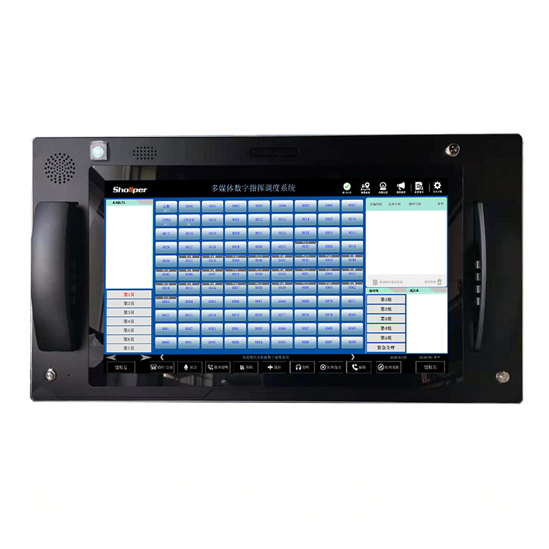
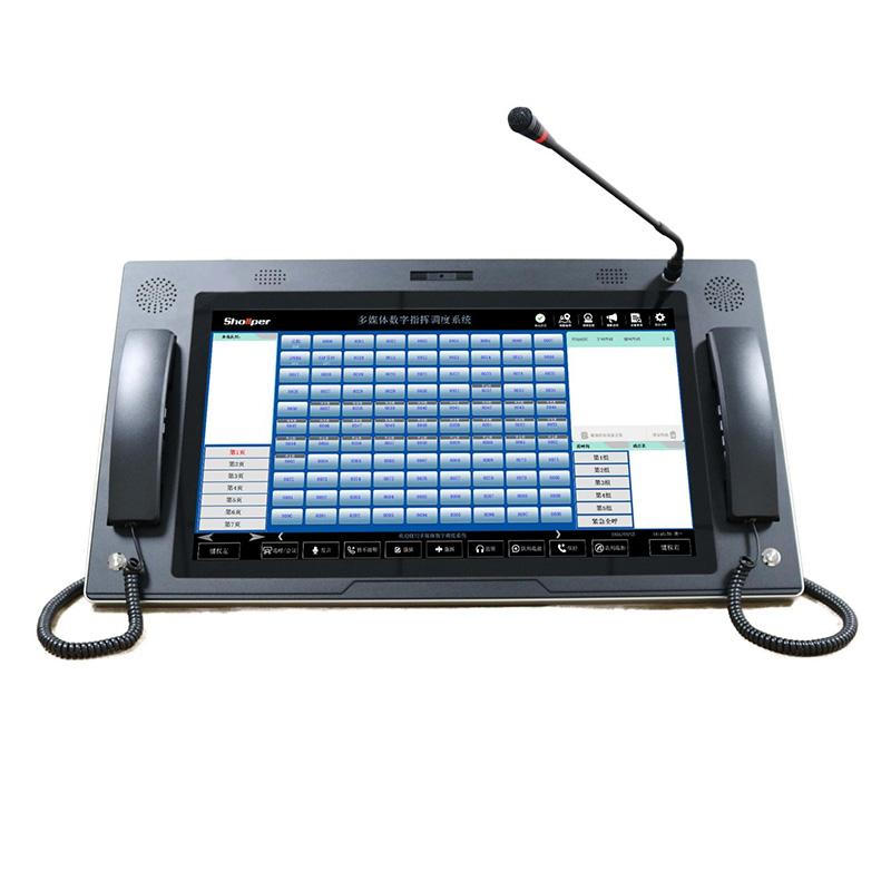
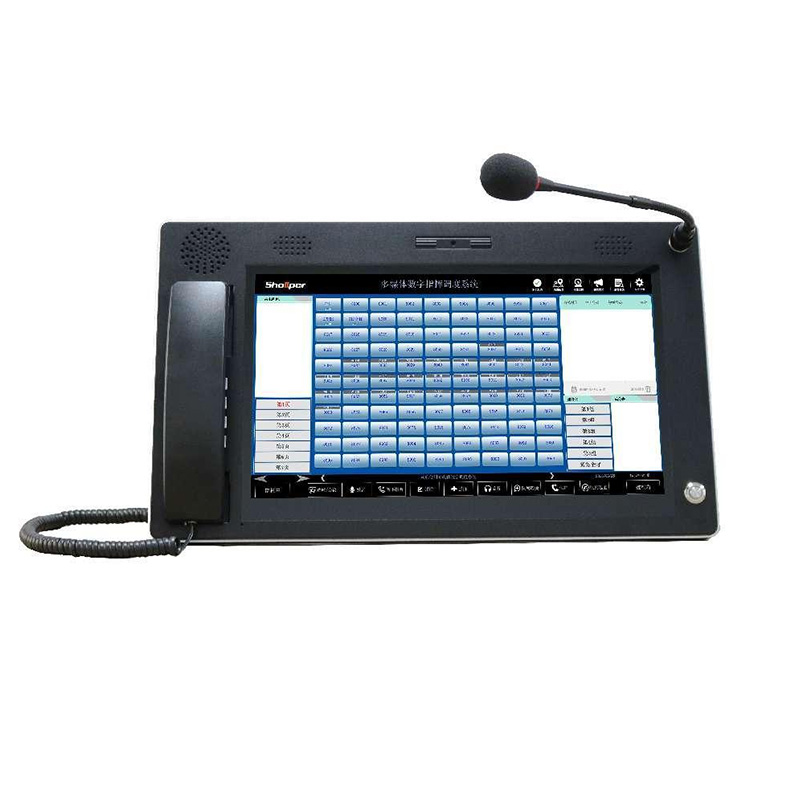
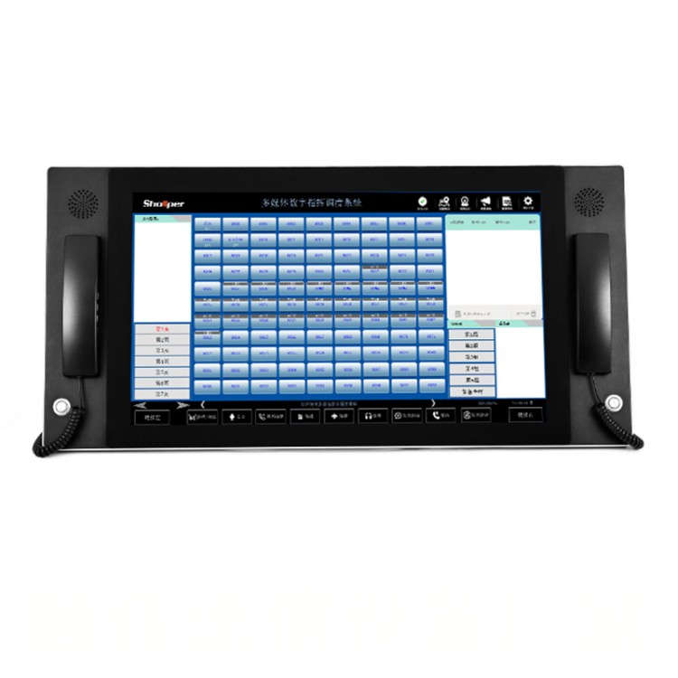
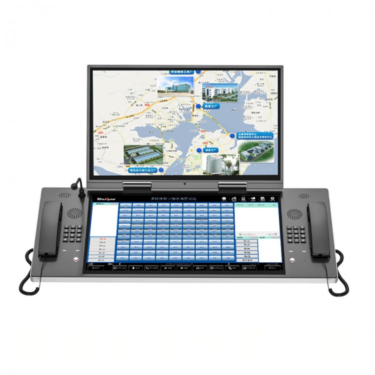
2. 21.5-inch touch screen dispatch console
21.5-inch PC-type dual-handled touch screen control console is a newly designed LCD industrial-grade touch screen control console with an elegant and generous appearance. The screen features a brand new 21.5-inch 16:9 high-brightness, low-power consumption, and environmentally friendly LCD wide screen, providing clearer and more atmospheric text display; paired with capacitive touch screen technology, it achieves a perfect blend of aesthetics and practicality; the operation interface is intuitive and clear, making it easier to use; it integrates an industrial-grade low-power embedded mainboard, supports CF, HDD, and has multiple I/O interfaces.
Structural Parameters
Surface Treatment: Panel with black sand grain baked paint, color black, edges in silver.
The cabinet structure: surface baked paint treatment, aesthetically pleasing, lightweight, and excellent heat dissipation performance.
Handset Phone: 2 built-in custom phones, one-touch hands-free.
Installation Method: 21.5-inch Flush Mount Desktop
Overall Weight: 17 kg
Overall Dimensions: 720mm x 336mm x 85mm
Operating Voltage: 220V
System Parameters
Processor: I5-4200U series processor
Memory: 4G DDR3 / 8G DDR3
Hard Drive: 500G / 1TB
Expanded Interfaces: VGA Port, HDMI Port
I/O Ports: 1*RJ45, 4*USB, 2*Phone Line LAN, 1*AUDIO
3. Comprehensive Utility Tunnel Emergency Telephone Dispatch System Software

Meeting: Press this button and then directly click the User button to form a temporary phone conference. The selected users will automatically join the temporary meeting.
Speech: When the ad-hoc conference key is also pressed and activated, pressing this key followed by selecting the corresponding user key allows the extension to switch from listener to speaker mode; when the ad-hoc conference key is not pressed, i.e., inactive, pressing this key and then selecting the corresponding user key toggles the extension between listener and speaker modes.
Reject: When the host sees the interface prompt indicating another incoming call during an ongoing call, clicking this button will send a busy tone to the incoming extension.
Force Insert: After clicking this button, the host can insert into an ongoing call on a substation to form a conference call. Both the host and the inserted substation are in listener mode during insertion (if the speak button is active during force insertion, it will become a multi-party call after insertion).
Force Disconnection: Click this button to disconnect any active extension from the host.
Full Connect: Click this button to answer all incoming calls simultaneously and form a conference call.
Priority: In case of an emergency where multiple extensions call in simultaneously and the main unit must selectively answer or cannot answer and must initiate a call-out to report the situation, press the priority call. The main unit will pick up to listen to the dial tone and then proceed as desired.
Monitor: Press this key to listen in on any extension currently on a call.
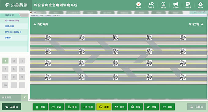
Software supports custom diagrams. Based on the actual conditions of each pipeline project, it can draw corresponding internal channel diagrams. The placement of individual extensions can be marked on the map, allowing direct dialing of extensions by simply clicking the phone icon on the map. Specific map click information is illustrated as follows:
The specific extension location can be set according to actual circumstances.
The pipeline diagram can be modified as per actual conditions.
5. Pipeline Corridor Scheduling System Framework Diagram