


KS-10 Type Axial Connection Gate Flowmeter |
![]()
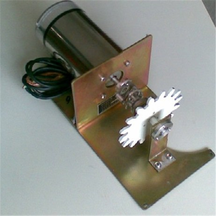
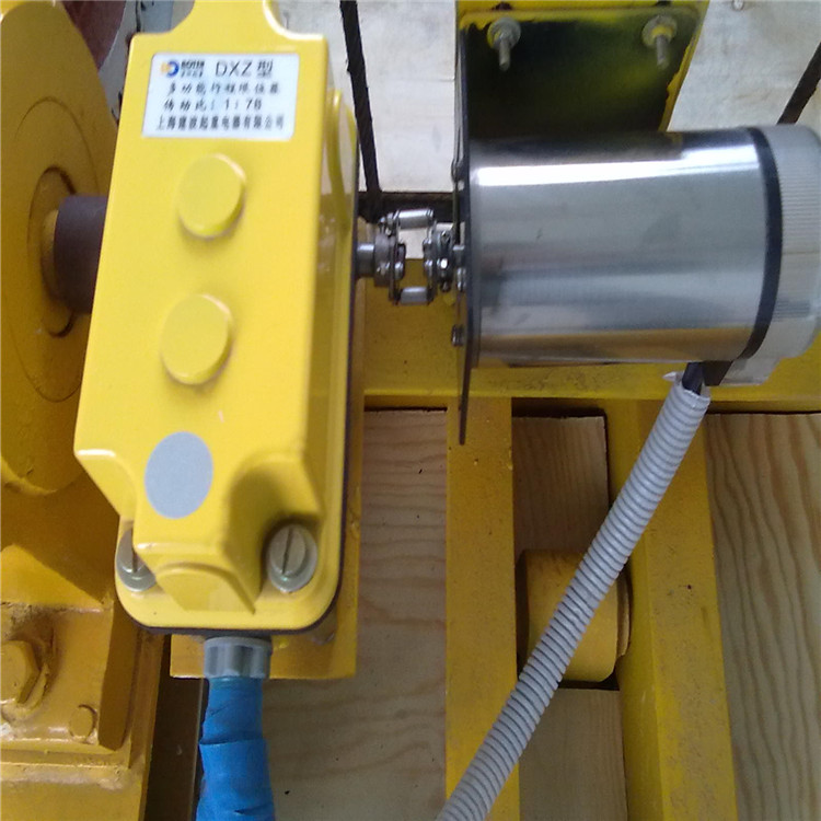
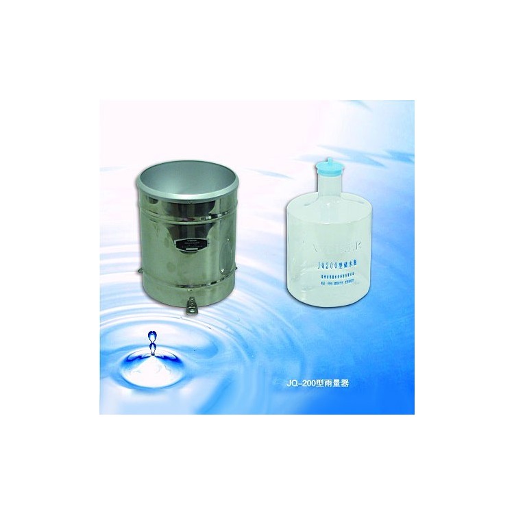
1 Function and Application The KS-10 type shaft-connected gate position gauge is suitable for measuring the gate opening of rivers, lakes, reservoirs, ship locks, hydropower stations, and supply and drainage projects. It can be coupled with gates using coaxial, sprocket, gear, and other direct connection methods. The instrument itself features an integrated stroke control switch that allows for direct setting of stroke limit control points. Additionally, this series of instruments can be connected with gate opening and closing machinery control devices and electrical displays to form a display and control system; connected to computer systems to form comprehensive measurement and control systems for hydropower stations, gates, and water levels; and connected to communication devices, serving as digital terminal equipment for hydrological automatic measurement and reporting systems and hydrological satellite remote sensing systems. This instrument is suitable for measuring the opening and controlling the stroke limit on flat gates, arched gates, screw gates, and winches. 2 Principle of Operation KS-10 Type Axial Connection Gate Position IndicatorComposed of mechanical or photoelectric encoders, stroke switch units, and corresponding couplers. The gate movement drives the encoder to rotate through the coupler, thereby outputting Gray code signals corresponding to the gate position and the corresponding mechanical stroke on/off signals. The resolution of the KS-10 type shaft connection position indicator is:0.5 cm or 1 cm.The operation process is as follows: When the gate moves vertically or rotates, the coupler connected to the gate synchronously moves as well. The coupler then drives the main shaft of the encoder, allowing the encoder to output an electrical signal (Gray code) corresponding to the gate position through its electrical socket. For flat gates, the output signal is decoded via hardware or software for display and observation purposes. For arched or V-shaped gates, the Gray code is automatically converted or digitally processed by an electric display or computer and then outputted. As the encoder rotates, the central axis of the integrated stroke switch assembly also rotates synchronously through the reducer. Upon reaching the limit position, it outputs a "closed" or "open" signal to the controller. 3 Technical Specifications a.Measurement Range: KS-10-B (Mechanical Encoder): 0~10m KS-10-G (Photoelectric Encoder): 0-20m b.Resolution: 1cm (mechanical encoder) 0.5, 0.1 cm (optical encoder) c.Output Code: Mechanical Encoder: Gray Code 10-13 bits Photoelectric encoder: Gray code 13 to 16 bits e.Transmission Distance: 500 meters or less f.Coupling Methods: shaft connection coupling, gear coupling, or sprocket coupling. g.Output Form: (1) Break and Make Contacts: 3A/220VAC (2) OC Door: 30mA/30VDC. 3.1 Communication Interface (Optional) RS485 Interface: MODBUS protocol or others. (2) 4-20mA analog signal output. 3.2 Application Environment aAmbient Temperature: -25℃ to 85℃ bRelative Humidity: <90% (at 40℃) Power Voltage: 12~24VDC. 3.3 Electric Display (Optional)  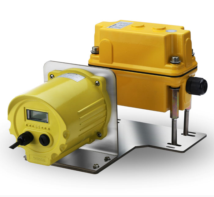 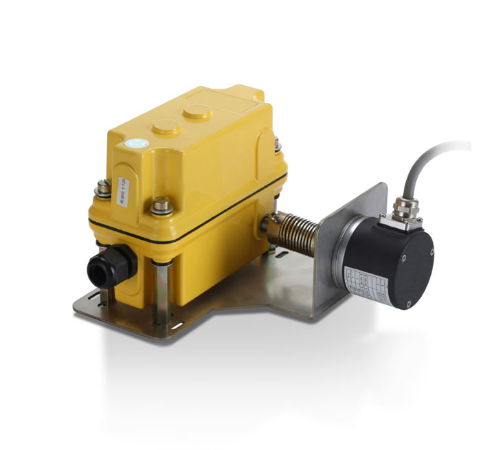 |