

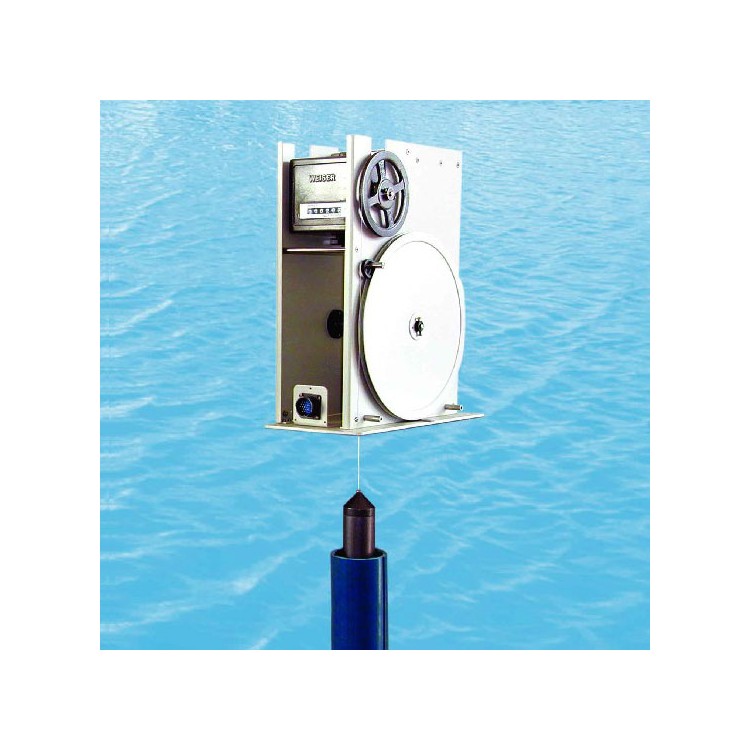
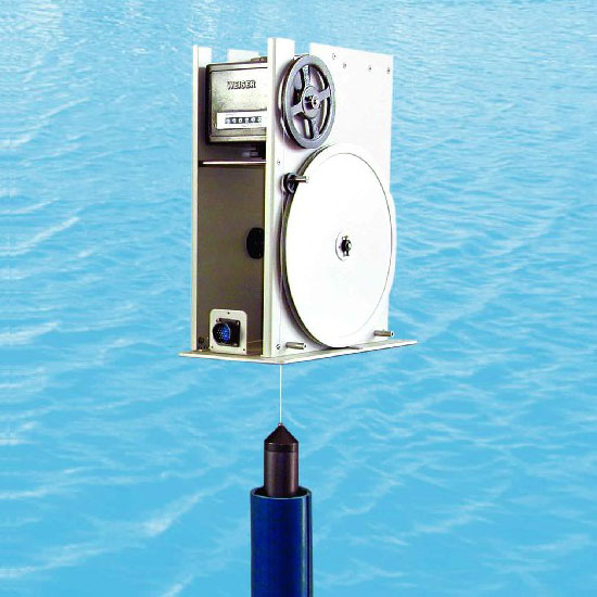
WFX-40 Submersible Fine Well Water Level Gauge |

![]()
1. Overview |
WeChat Official Account

Scan to follow Official Account


Unit Price
$1000.00/Tai
Brand
Xuzhou Weisi
MOQ
1Tai
Platform Service
Supplier Verified
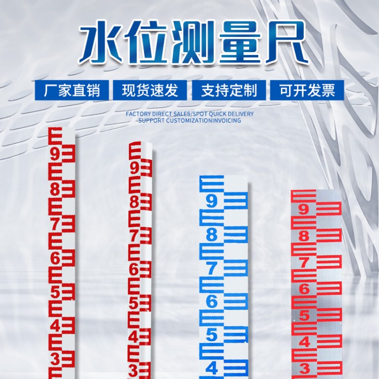 Level Gauges, Level Gauge Manufacturers, Level Gauge Prices, Water Level Reading
Jiangsu Xuzhou
Details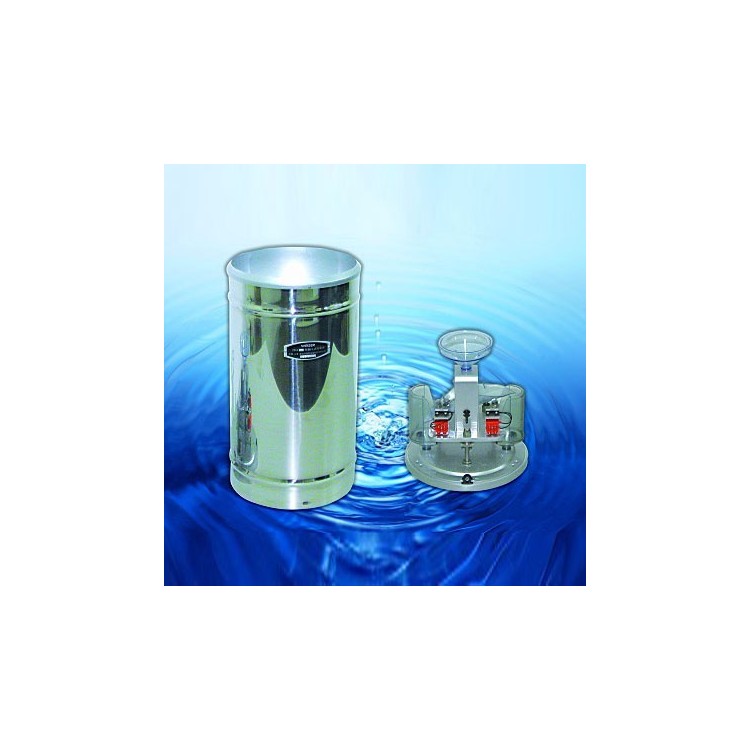 JD10 Type Bucket Rain Gauge, Single Bucket Rain Gauge, Double Bucket Rain Gauge
Jiangsu Xuzhou
Details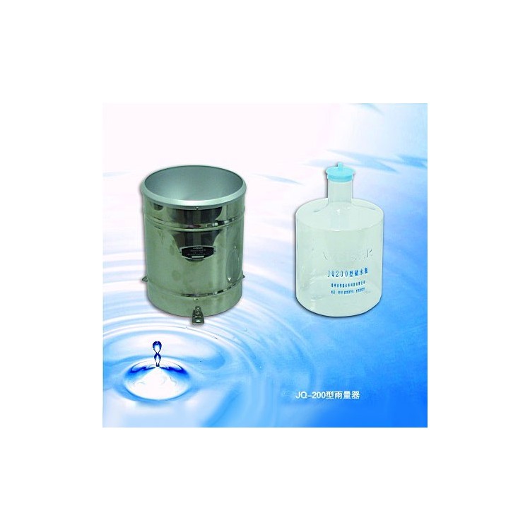 JQ200 Rain Gauge, Manual Rain Gauge, Split-Type Rain Gauge
Jiangsu Xuzhou
Details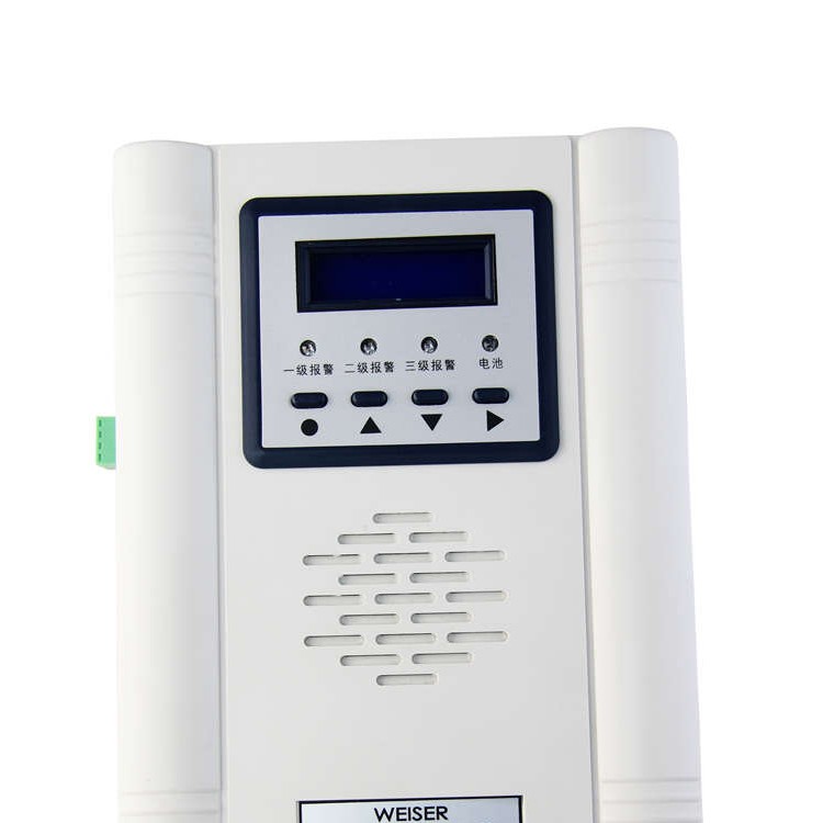 JBD-2 Rain Alarm, Simple Rain Alarm, Wes Rain Alarm
Jiangsu Xuzhou
Details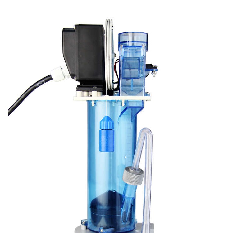 JFZ-01 Digital Rain Gauge, Digital Rain Gauge, Digital Rain Gauge Manufacturer
Jiangsu Xuzhou
Details Winter is here; what maintenance tasks are required for outdoor water quality monitoring equipment?
2024-12-23
 HG30-E Multi-functional Calibration Instrument (Multimeter Calibrator)
2024-11-28
 HG6503 Multi-functional Precision Calibration Instrument
2024-11-28
 Wing Span Semi-Trailer Manufacturers, Integrated Wings Container Semi-Trailer Transport Market Trends
2024-11-10
 Manufacturer of winged semi-trailers, integrated wing container semi-trailer transport market行情
2024-11-10
Level Gauges, Level Gauge Manufacturers, Level Gauge Prices, Water Level Reading
JD10 Type Bucket Rain Gauge, Single Bucket Rain Gauge, Double Bucket Rain Gauge
JQ200 Rain Gauge, Manual Rain Gauge, Split-Type Rain Gauge
JBD-2 Rain Alarm, Simple Rain Alarm, Wes Rain Alarm
JFZ-01 Digital Rain Gauge, Digital Rain Gauge, Digital Rain Gauge Manufacturer
 JD-05G Type Rain Gauge, Wesco Rain Gauge, Rain Gauge Manufacturing
Product Details
Specs
Gallery
Brand:
Xuzhou Weisi
Unit Price:
$1000.00 / Tai
MOQ:
MOQ1Tai
Total:
10000Tai
Address:
JiangsuXuzhou
Delivery:
3days
WFX-40 Submersible Fine Well Water Level Gauge |
![]()
1. Overview |
Disclaimer:Info provided by user, user liable for authenticity, accuracy & legality. Zhongshang114 assumes no liability.
Tip:Confirm supplier qualification & quality before purchase to avoid risks.
| Unit Price | $1000.00 / Tai | |
| Sales | None | |
| Delivery | JiangsuXuzhou3dayswithin | |
| Stock | 10000TaiMOQ1Tai | |
| Brand | Xuzhou Weisi | |
| Water Level Fluctuation: | 0-10m: 0-20ft; 0-30ft; 0-40ft; 0-80ft; | |
| Water Level Encoder Resolution: | 1 cm | |
| Accuracy of Measurement: | ≤0.2% | |
| Expiry | Long Valid | |
| Update | 2024-07-05 11:15 |
Wuxi Weisi Water Technology Co., Ltd.Published byWFX-40 Buoy Type Fine Well Water Level Gauge, Xuzhou Weisi Buoy Water Level Gauge, Buoy Water Level Gauge ManufacturerGallery Lib


Contact Merchant


Join
Successful Enterprise Join, Enjoy Multiple Privileges
Join Hotline:4006299930
Please scan with mobile phone


Customer Service
Service Hotline:4006299930


Official Account
WeChat Official Account, Get Business Opportunities
Scan to follow WeChat
Top


