


1、 The purpose of an open channel flowmeter is to be used in conjunction with a measuring weir to measure the flow rate of water in an open channel. Mainly used to measure the flow rate of sewage discharge outlets of sewage treatment plants, enterprise and government liquid units, and urban sewers. Due to the use of ultrasonic waves passing through the air, this instrument measures in a non-contact manner. Therefore, in the case of sticky and corrosive liquids, it has higher reliability than other forms of instruments. 2、 The working principle of open channel flowmeter is that the physical quantity directly measured by the open channel flowmeter is the liquid level. When used for measuring flow in open channels, a measuring weir groove is installed on the open channel. The measuring weir channel converts the flow rate in the open channel into the height of the liquid level. The instrument measures the water level in the measuring weir groove, and then calculates the flow rate based on the corresponding water level flow relationship of the measuring weir groove. The commonly used measuring weirs and channels include right angled triangular weirs, rectangular weirs, and Bacher channels (Figure 3). When using an ultrasonic open channel flowmeter, it is necessary to know the corresponding relationship between the water level and flow rate of the dosing weir tank during installation. The water level flow relationship of the measuring weir can be found in the national metrological verification regulation "Open Channel Weir Flow Meter" JJG711-90. Once the Bacher trough knows the throat width b, it can use the corresponding formula to calculate the relationship between water level and flow rate. There are corresponding formulas for right angled triangular weirs and rectangular weirs. But it also depends on the size of the installation channel. When determining the water level flow relationship, the triangular weir is related to the channel width B, opening angle, and upstream weir height p. The rectangular weir is related to the channel width B, opening width b, and upstream weir height p. Principle of Ultrasonic Liquid Level Measurement: This instrument uses ultrasonic echo ranging method to measure liquid level. The probe is fixedly installed above the water level observation point of the measuring weir. Aim the probe at the water surface. The probe emits ultrasonic waves towards the water surface. The working principle of the instrument: The instrument controls the probe to emit and receive ultrasonic waves. Measure the transmission time of sound waves to calculate the liquid level in mm. By checking the water level flow meter, convert the liquid level into flow rate (unit: liters/second). Instrument display: The instrument displays the liquid level height, instantaneous flow rate, and accumulates the instantaneous flow rate over time to obtain the cumulative flow rate. The instrument output includes 4-20mA current analog quantity; The switch quantity of the relay (to be ordered and selected); RS485 digital signal; What are the technical parameters of the Bacher trough open channel flowmeter? Flow range: 0.1 liters per second to 10 cubic meters per second? Traffic uncertainty: 5% 3)? Static pressure ranging: 2.4 meters? Probe blind spot: 0.4 meters (cannot be used for measurement within 0.4 meters from the flange of the probe) 5)? Distance measurement error:<0.4%? Or ± 3 millimeters (within 1 meter range) 6)? Water level resolution: 1mm7)? Accuracy: Level 0.5 (8)? Medium temperature: 0-60 ℃ 9)? Pressure flow, free flow 10)? Channel type: Channel type 11)? Protection level: IP6512)? Power supply: 220VAC 50HZ13)? Connection method: flange 14)? Instrument display: displays instantaneous flow, cumulative flow, and historical records of more than 4 years. Power consumption: ≤ 15W15)? Power supply voltage? : 24VDC ± 10% or 12VDC ± 10% (24VDC is recommended for 4-20mA) 16)? Customization of other power supply voltages (17)? Losing???? Out? RS485, M-BUS (capable of meter reading with centralized M-BUS collectors such as electric meters), 4-20mA output, 18)? Transmission protocol? MODBUS protocol, Nine Wave protocol 19)? Range and zero position: digitally adjustable 20)? Start time? Within 2 seconds (21)? Environmental temperature? 0 to 70 ℃ (22)? Display method? LED or LCD display (with backlight) 23)? ambient humidity? 5% -95%, no condensation, 24)? Zhen???? Moving? :≤10g,f≤55Hz, Amplitude ≤ 0.5mm25)? Take it???? The ground? In areas with high electromagnetic interference, the transmitter and cable shielding layer should be well grounded? Fine???? Degree? :±0.2%,±0.5%27)? Line???? Sex? :±0.2% ,±0.5%28)? Electrical interface? :M20×1.529)? Can the sensor heating device be selected according to the environment (30)? Expansion port: external Doppler ADCP adaptive port (I) JZYBS-D51B-2 standard Bacher slot installation
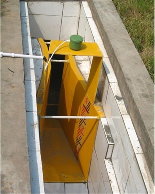
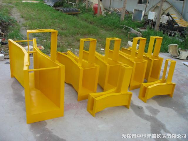
(1) Preparation for civil engineering installation of open channels: Before installation, the terrain must be inspected first, and the inlet must be higher than the outlet to ensure a water level difference and smooth outlet. This is the key to successfully installing the Bacher trough open channel flowmeter. Figure 3-35 Simulation diagram of Bacher metering tank (2) Requirements for placing the Bacher tank into an open channel: ① There is a water level difference at the downstream discharge outlet of the Bacher tank, and the discharge is smooth. If the water level difference is not enough, the Bacher tank should be raised to increase the water level difference. ② Ensure that the straight section in front of the Bacher groove has an installation distance of 3-5 times that of the groove body. (3) Reinforce the Bacher trough by pouring concrete on both sides to ensure that all water flows through the Bacher trough. During reinforcement, the Bacher groove should be kept horizontal on both sides to prevent tilting and deformation. When reinforcing, the centerline of the water flow in the Bachel trough must coincide with the centerline of the weir trough. (4) After the installation of the Bacher slot for instrument wiring, wait for the concrete to solidify before proceeding with instrument installation and debugging. Generally, installation and debugging should be carried out by instrument technicians. If the signal transmission cable of the split is far away, users can extend it themselves, and the distance is generally within 20 meters. Otherwise, field connection experiments should be conducted.

The measurement range is large, and the flow measurement is not affected by the backflow of tributaries. The flow sensor is not affected by floating sediment, bubbles, and significant changes in water level during measurement. It has a simple structure, small volume, and easy installation for water resistance. Standard channels do not require modification and can be installed directly, with low installation and construction costs. The instrument display has complete output functions and can display measurement data such as water level, flow rate, flow rate, and cumulative flow rate. It also has an RS-485 communication interface. It has the function of water level, mud level, and flow rate exceeding the limit alarm. It has data saving function, which can save the set parameters and flow values in case of long-term power outage.
1. The accuracy level and function of the instrument are selected based on measurement requirements and usage scenarios to achieve cost-effectiveness. For example, in situations such as trade settlement, product handover, and energy measurement, higher accuracy levels such as 1.0, 0.5, or higher should be selected; For process control applications, choose different accuracy levels according to control requirements; In some cases where only the process flow is detected without the need for control and measurement, a slightly lower accuracy level, such as 1.5, 2.5, or even 4.0, can be selected. In this case, a low-cost plug-in open channel flowmeter can be used.
2. When measuring medium flow rate, instrument range, and caliber for general medium measurement, the full flow rate of an open channel flowmeter can be selected within the range of 0.5-12m/s for measuring medium flow rate, which is relatively wide. The selection of instrument specifications (caliber) may not necessarily be the same as the process pipeline, and should be determined based on whether the measured flow range is within the flow rate range. That is, when the pipeline flow rate is too low to meet the requirements of the flow instrument or the measurement accuracy cannot be guaranteed at this flow rate, the instrument port diameter needs to be reduced to increase the flow rate inside the pipeline and obtain satisfactory measurement results.
3. Fluid characteristics mainly refer to the pressure, temperature, density, viscosity, compressibility, etc. of gas. As the volume of gas varies with temperature and pressure, compensation and correction should be considered.
4. Instrument performance refers to the accuracy, repeatability, linearity, range ratio, pressure loss, initial flow rate, output signal, and response time of the instrument. When selecting a flowmeter, careful analysis and comparison of the above indicators should be carried out to select an instrument that can meet the flow requirements of the measuring medium.
5. The installation conditions refer to the flow direction of gas, the direction of the pipeline, the length and diameter of the upstream and downstream straight pipes, the spatial position, and the fittings, all of which will affect the accurate operation, maintenance, and service life of the gas flow meter.
6. Economic factors refer to purchase costs, installation costs, maintenance costs, calibration costs, and spare parts, which are also affected by the performance, reliability, and lifespan of gas flow meters. Considering the flow measurement characteristics of urban water supply channels, industrial water supply and drainage channels, sewage treatment channels, etc., the following factors should be taken into account when selecting appropriate measurement methods.
1) Waterway size and shape, flow velocity range, flow rate, and minimum flow rate;
2) Measurement requirements;
3) Location and environmental conditions for flowmeter installation;
4) Liquid condition, cleanliness, solid concentration, corrosiveness;
5) On site allowable drop (or raised water level) and channel slope;
6) Materials of instrument components in contact with liquids;
7) The selection of ultrasonic flowmeter and electromagnetic flowmeter requires investigation of liquid turbidity or conductivity separately, and their requirements can refer to those of ultrasonic flowmeter and electromagnetic flowmeter.
Estimate channel flow and raise water level
For newly established units, the channel flow rate and proposed installation location can be calculated through the process flow, and then the instrument specifications can be selected. For old enterprises to purchase instruments, it is necessary to estimate the flow rate of existing channels and confirm the allowable upstream water level of the instruments; The determination of the specifications and flow range of the flow meter depends on two factors: the peak flow rate of the channel and the allowable raised water level.
(1) Estimate peak traffic volume
There are usually two methods: float method and daily emission estimation method.
1) The float method can be used to measure and estimate flow in existing open channels. When selecting the flow rate, two people stand next to a straight channel at a distance of L (20-50m), with one person upstream placing a float (usually a wooden disc) and the other person downstream starting the timer at the moment of placing the wood chips. When the float arrives, the timer stops, and the time t is obtained. The surface flow velocity of the channel is calculated as υ m/s (υ=L/t). By measuring the channel flow cross-sectional area Am2 again, the K correction factor in the flow Q equation can be estimated from equation (5). As the surface flow velocity is greater than the average flow velocity, it is generally taken as 0.84~0.90
2) Estimating peak flow rate Qp from daily emissions Qd can be done using the float method or a newly built system if conditions permit. The actual (or designed) emissions can be used to estimate peak flow rate, and the estimation formula is Ku - non-uniformity coefficient in equations (6) or (7). For uniform continuous emissions, it can be taken as 1.1-1.2;
H ---- The cumulative number of hours of centralized emissions per day. If it is uneven continuous emissions, it shall be calculated based on the hours of centralized emissions.
(2) Determine to raise the water level
Except for flow rate water level flow meters and non full pipe electromagnetic flow meters, the upstream water level must be raised after installing flow meters in the channel. For the newly designed canal system, the height of the raised water level can be determined comprehensively based on the measured flow range and surrounding environmental conditions. For existing channels, when selecting a flow meter, the impact of the upstream channel system water level rise (such as whether the water level will overflow the channel) should be considered, and then the instrument specifications should be selected based on the determined water level rise height and peak flow value.
The basic requirements for annual inspection and calibration are as follows:
1) If the environmental condition calibration is carried out in the calibration room, the environmental conditions should meet the laboratory's requirements for temperature, humidity, and other regulations. If calibration is carried out on site, the environmental conditions shall be based on the conditions that can meet the on-site use of the instrument.
2) As a standard instrument for calibration, the error limit of the instrument should be 1/3 to 1/10 of the error limit of the calibrated meter.
3) Although personnel calibration is different from verification, the personnel conducting calibration should also undergo effective assessment and obtain corresponding qualification certificates. Only certified personnel can issue calibration certificates and reports, and only such certificates and reports are considered valid.
The larger the flow in the open channel, the higher the liquid level; The smaller the flow rate, the lower the liquid level (see Figure 5a). For general channels, there is no definite correspondence between liquid level and flow rate. Because the same water depth and flow rate are also related to the cross-sectional area, slope, and roughness of the channel. Installing a measuring weir groove in the channel, the correspondence between the upstream water level and flow rate of the channel mainly depends on the geometric dimensions of the weir groove, as the gap of the weir or the contraction of the groove is smaller than the cross-sectional area of the channel. The same measuring weir tank is placed on different channels, and the same liquid level corresponds to the same flow rate. The measuring weir channel converts the flow into liquid level. By measuring the liquid level of the water flow in the measuring weir tank, and then reverse calculating the flow rate based on the corresponding water level flow relationship of the measuring weir tank.