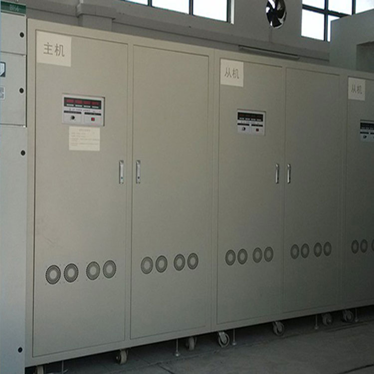


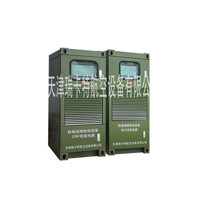
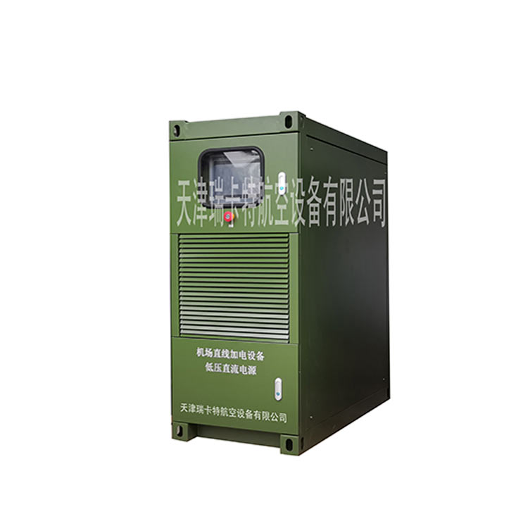
The Voltage and Frequency Stabilized Power Supply Series converts the municipal power through a power conversion circuit into the required voltage and frequency. Its main features include pure and reliable sine wave power output, low harmonic distortion, high stability in frequency and voltage regulation. It can simulate output characteristics of different voltages and frequencies worldwide, covering the entire industry's needs and fully complying with applications such as engineers' design and development, production line testing, product quality assurance inspections, lifespan testing, over-voltage/under-voltage simulation tests, power supply for imported equipment, and production lines. Additionally, this power system supports 400Hz for aerospace applications.
High reliability
All major components are imported, featuring original Mitsubishi IGBT inverter modules, driven and protected by the original Japanese Mitsubishi mechanism, with a comprehensive drive and protection circuit ensuring reliable operation of the IGBT.
2. Fast dynamic response speed ()
Utilizing a dual-loop feedback circuit, the inner loop current loop ensures non-linear load waveforms are not distorted; the outer loop voltage loop guarantees sudden load voltage drop is less than 1%, with a response time less than 2mS. The control circuit is an analog circuit, featuring strong anti-interference capability and no system crashes. Some manufacturers use digital control sampling that requires A/D conversion, calculation, and D/A conversion, resulting in a longer control process, slower response time, weaker anti-interference ability, and a higher likelihood of system crashes.
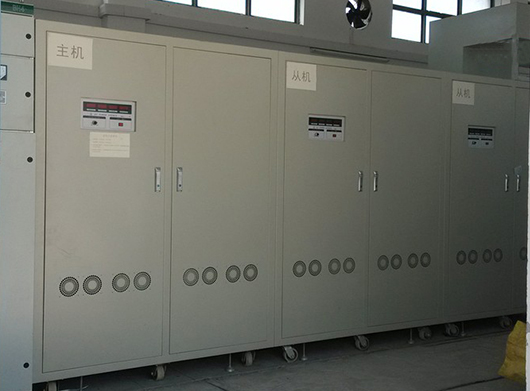
3. Three-phase power can accommodate any unbalanced load
Three-phase power supply can be synchronized in three phases or individually adjusted in single phases. The main circuit and control circuit of the three-phase power supply are designed according to three independent single-phase power sources. The main circuit adopts a rectifier-direct current-inverter structure, including rectifiers, DC filters, inverters, AC filters, and transformers, among other components. The three single-phase inverter circuits have an output phase difference of 120 degrees. They are electrically independent on the primary side of the transformer and connected in a star configuration on the secondary side to output the required three-phase AC power. Voltage and waveform control for single-phase output utilizes three independent single-phase controllers, allowing any phase of the three-phase power supply to be used as a single-phase power supply independently. This also accommodates any unbalanced load, greatly enhancing the power supply's load adaptability. It truly achieves any load imbalance.
4. User-friendly interface, source and display integrated, high measurement accuracy
Voltage, frequency, current, power/power factor four-window measurement display, accuracy of 0.5 class, source meter integration.
5. High loading capacity
Power components are applied reasonably, capable of withstanding 3 times the rated current without causing voltage drop.
6. Excellent Stability
Frequency stability ≤ 0.01%, load stability ≤ 1%, the output frequency is generated by a quartz oscillator, hence it is extremely stable and accurate.
| Specification RWF33______ | 500W - 1000KVA | |
| Input | Rated Voltage | 220±%/380V±10% 50Hz±2% |
| Output | Rated Voltage | Line voltage adjustable from 0-150V (output voltage can be customized according to customer requirements) |
| Stabilized Voltage Accuracy | ≤±0.5% (full scale) | |
| Frequency | 60Hz (47-70Hz continuously adjustable), frequency stability 0.1% (full scale) | |
| Dynamic Characteristics | Overshoot and recovery time meet GJB572 requirements. | |
| Waveform distortion | Pure sine wave, THD < 3% (linear load test) | |
| Source Adjustment Rate | ±0.2% (Full Scale) | |
| Load Adjustment Rate | ±1% (Full Scale) | |
| 41/2-digit display | Voltage Display | True RMS 0.1V |
| Current Display | True RMS Value: 0.1A | |
| Frequency Display | 0.1HZ | |
| Protect | Output short circuit, overcurrent, overvoltage, overload, internal overheating | |
| Reliability | MTBF: 8,000 hours; average repair time: 3 hours | |
| In-and-out line method | Bottom side in-out lines | |
| Cooling method | Air-cooled | |
| Inlet and outlet ventilation | Bottom and side intake, top and back exhaust | |
| Protection Level | IP40 | |
| Environment | Application Environment | Temperature -10 to 45°C, Humidity 0 to 90% non-condensable state |
| Altitude | ≤2000m | |