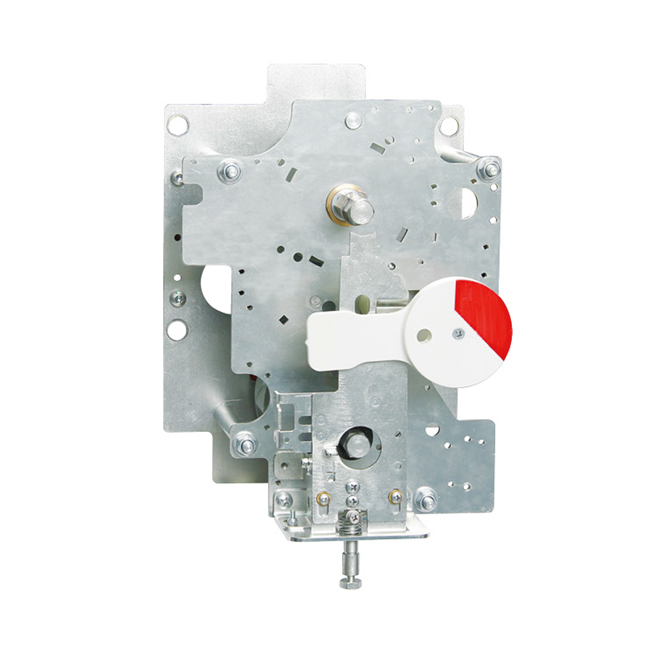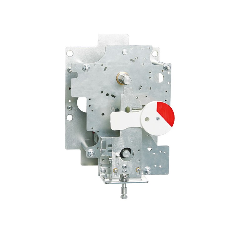


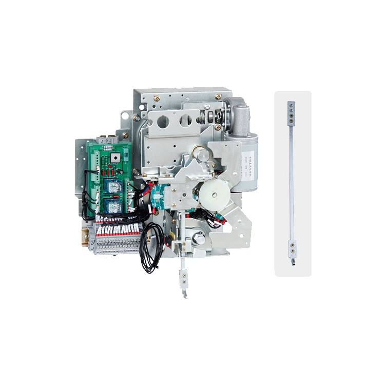


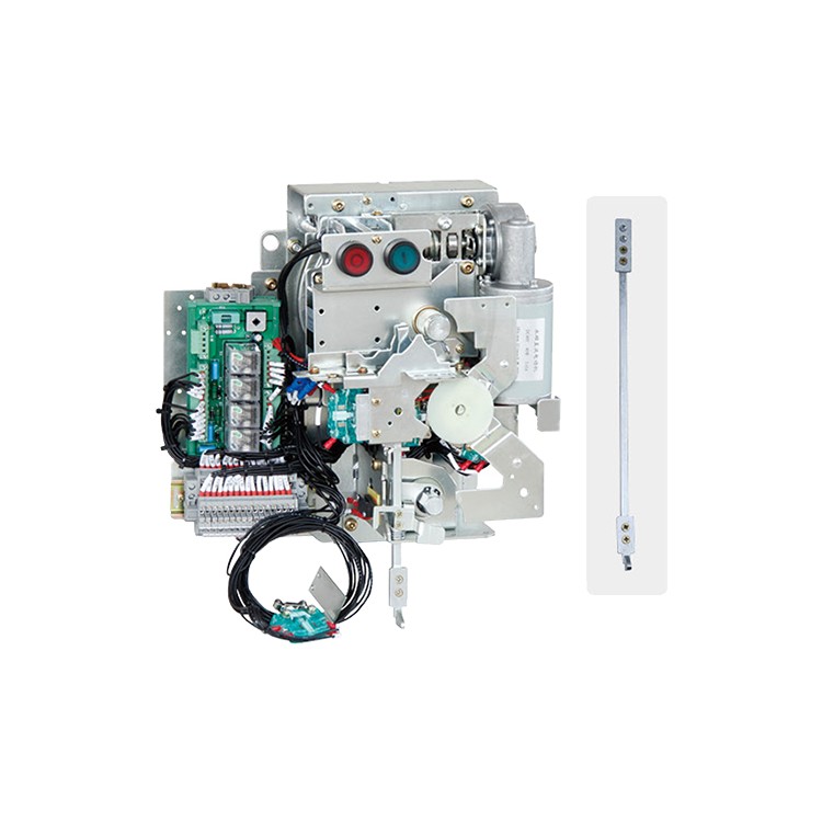
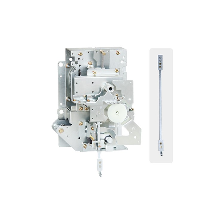

The KJC-06 series incoming line operation mechanism is a manual hard-wired pull-down door mechanism for the SF6 gas-insulated switchgear's ring main unit. It features three operational positions for common, separate, and grounding, as well as a five-protection and linkage function.
This series of products is factory-shipped after full inspection and complies with the GB 3804-2017 C3.6kV 40.5kW High Voltage AC Load Switch, GB 3906-2020 [AC Metal-Enclosed Switchgear and Control Gear, 3.6kV-40.5kW AC], and GB/T 11022-2020 (Common Technical Requirements for High Voltage AC Equipment and Control Gear) standards.
User Operation Instructions
Closing operation:
After verifying the product is normal and free of deformation, secure the mechanism and load switch by aligning them through a three-position motion on the pressure box of the incoming line cabinet. Insert the hexagonal handle into the hexagonal shaft on the upper part of the mechanism, rotate it clockwise by approximately 90 degrees to complete the closing operation of the load switch. When the load switch is in the closed position, the grounding operation hole will be sealed by the open/close indicator. Users must not force the grounding operation against the indicator sign, otherwise, it will violate the five-prevention operation requirements.
Circuit Breaker Operation:
In the closed position of the load switch, insert the hexagonal handle into the hexagonal shaft at the top of the mechanism, and rotate it counterclockwise approximately 90 degrees to immediately open the main circuit of the load switch. This opening operation can only be performed when the load switch is closed. When the main switch is open, operations such as closing the main switch or grounding the switch can be carried out. This operation must not be performed forcibly against the instructions on the signage.
Grounding operation:
When the main switch is in the split position, insert the hexagonal handle into the hexagonal shaft on the lower part of the mechanism and rotate it clockwise by approximately 90 degrees to close the grounding circuit, or counter-clockwise by approximately 90 degrees to open the grounding circuit. When the grounding is in the closed position, the load switch operating hole will be sealed by the opening and closing indicator sign. Users must not force the operation of the load switch against the sign's indication; otherwise, it will violate the five prevention operation requirements.
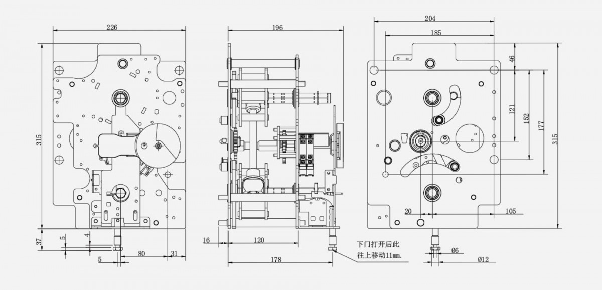
Actuator dimensions and installation dimensions