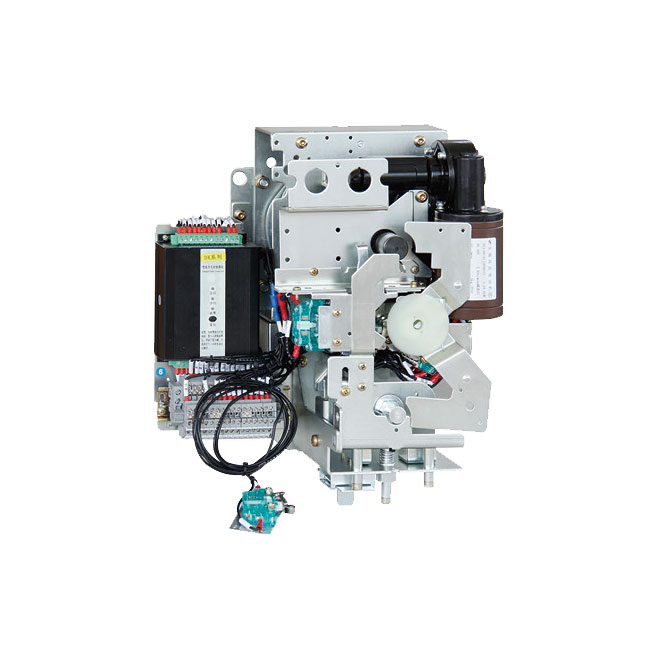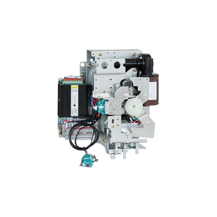


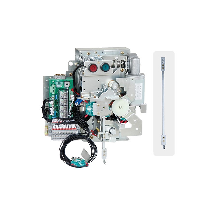

KICD-03/MX Intelligent Electric Operation Solution, featuring an MCU chip integrated circuit for intelligent judgment of the closing/opening state of the load switch, performs electric operations on the mechanism according to customer instructions, enabling both local and remote closing/opening functions. It offers protection against undercurrent or overload due to jamming, ensuring the safety of critical components in the mechanism. The controller has a function to signal equipment faults, greatly facilitating daily maintenance.
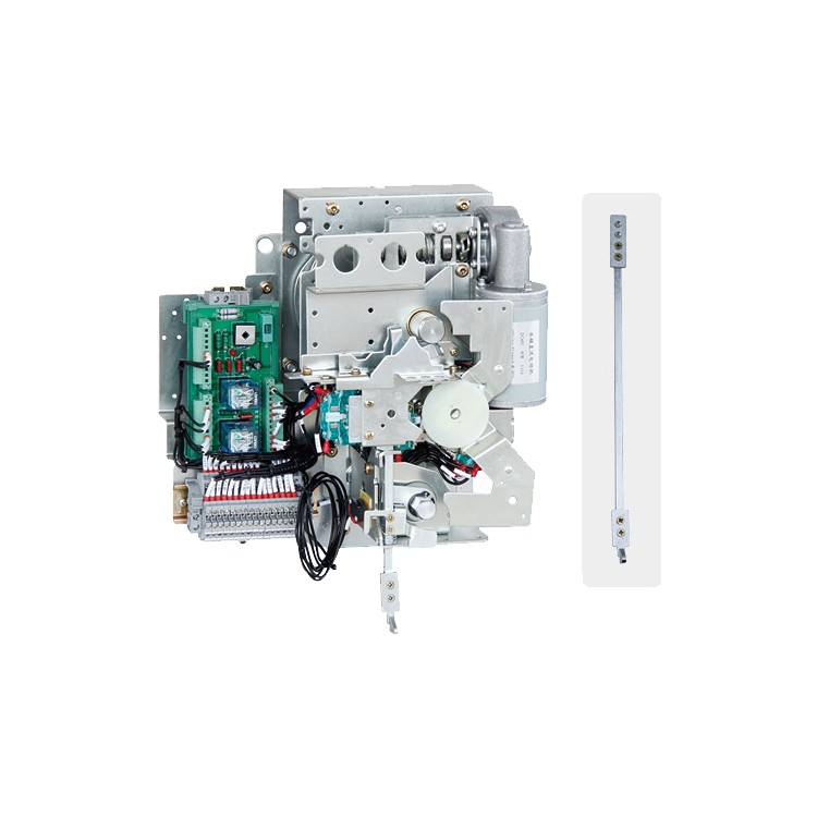
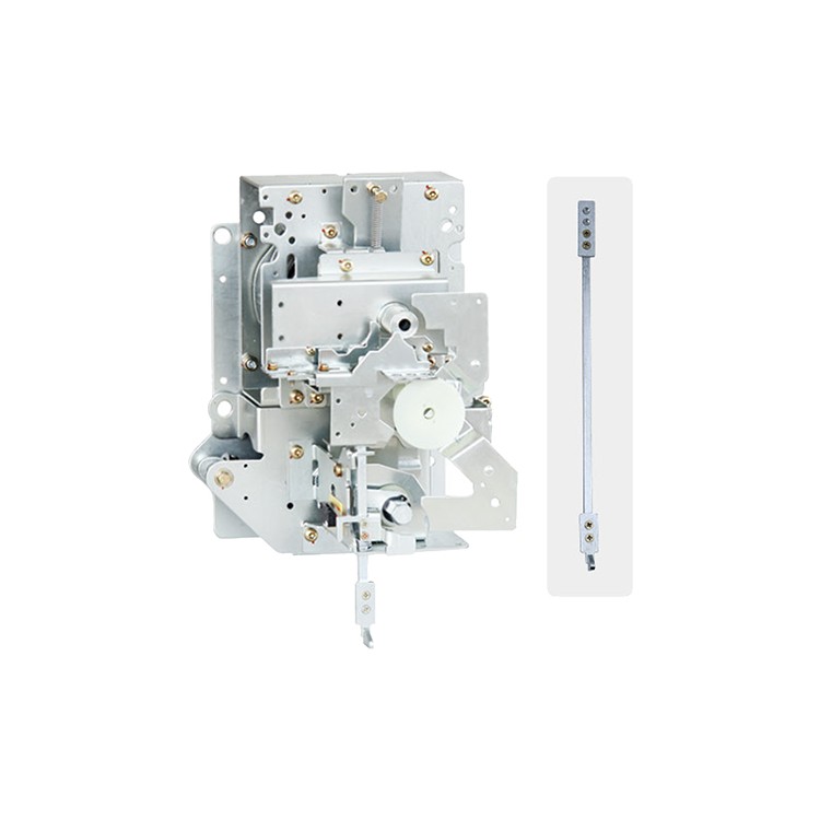
KJCD-03/NX Standard Electric Operation Plan, featuring PCB terminal integration and electric operation of mechanisms achieved through relay contacts within the controller. It lacks motor protection and fault alert functions, classifying it as an economical electric operation solution.
This series of products is fully inspected and passes quality checks before leaving the factory. It complies with the requirements of G8 3804-2004 "AC High Voltage Load Break Switches 3.6KV-40.5KV," GB3906-2006 "AC Metal-Enclosed Switchgear and Control Equipment 3.6KV-40.5KV," and "High Voltage AC Load Break Switch-Fuse Combination Appliances."
User Operation Instructions
Circuit closing operation:
The mechanism is installed and secured in the cabinet. Insert the mechanism handle into the operation shaft located at the top of the mechanism, rotate it clockwise approximately 90 degrees. When the mechanism's coiled spring is compressed to the critical energy release point, it releases energy. Under the energy release force, the load switch is actuated to close the main circuit. During electric closing, power is supplied to the mechanism and a closing signal is given. The controller automatically detects the load switch's open/closed position and the status of each interlock circuit. If all circuits meet the conditions for closing, the controller automatically starts the mechanism motor to close the main circuit of the load switch. At this time, the mechanism grounding function is locked, preventing grounding operations.
Individual compartment operation
During manual disconnection, insert the mechanism handle into the operating shaft located at the top of the mechanism, rotate the handle counterclockwise approximately 90°. When the mechanism's coiled spring is compressed to the critical energy release point, release the latch to discharge energy. Under the energy release force, push the load switch to complete the main circuit disconnection. For electric disconnection, the user provides a disconnection signal. The controller automatically identifies the load switch's on/off position and the status of each interlock circuit. If all circuits meet the conditions for disconnection, the controller starts the mechanism motor to complete the main circuit disconnection of the load switch. In the disconnection state, operations for closing or grounding can be performed.
Grounding and circuit breaking operations:
Grounding Closure: Insert the mechanism handle into the grounding operation shaft at the bottom of the mechanism, rotate clockwise approximately 90°. The grounding energy storage spring releases energy instantly upon compressing past the midpoint, actuating the grounding switch to complete the grounding closure. At this point, the mechanism interlock locks, preventing main circuit closure.
Grounding Disconnect: Insert the mechanism handle into the grounding operation shaft at the bottom of the mechanism, rotate counterclockwise approximately 90 degrees. The grounding energy accumulator releases instantaneously when it reaches the midpoint of compression, pushing the grounding switch to complete the grounding disconnect. At this point, the mechanism interlock is in the open position, allowing for closing and opening operations on the load switch.
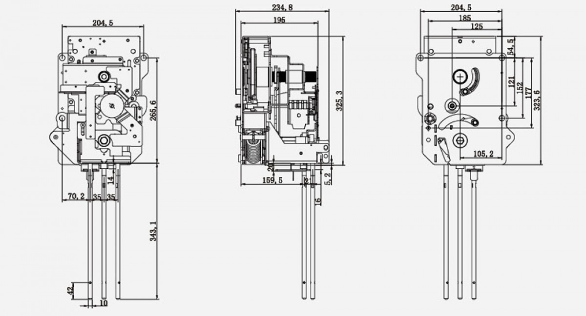
Actuator external and installation dimensions