


I. Overview
Our country started late in economic construction, but it has grown rapidly, causing many cities' road facilities to lag behind society.
Development pace, with many cities still adhering to outdated lighting systems, presenting significant drawbacks in their system models.
High energy consumption, requires professional electricians for management positions, inconvenient line maintenance, and limited flexibility in control system modifications.
Larger lighting discrepancies and issues.
Smart lighting control devices cater to various lighting application scenarios both domestically and internationally. With the continuous advancement of society, city...
The continuous development of urban road construction is leading to the gradual implementation of intelligent management in lighting control systems. As the primary lighting systems for city traffic roads, landscapes, shopping malls, airports, hotels, residential areas, gas stations, and more, they hold a significant position in the construction of urban infrastructure. Function:
Manual Control
Click the control panel button to manually control each loop and display the status of the loop switches in real-time. 2. Remote Control
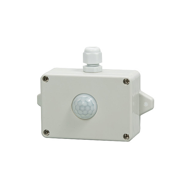
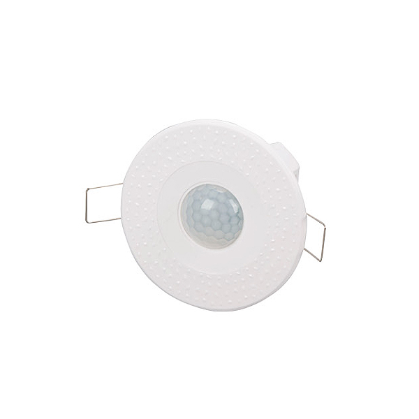
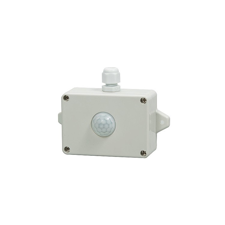
Infrared Sensors (custom interface), Microwave Sensors (custom interface), Photoelectric Sensors, 86 faces
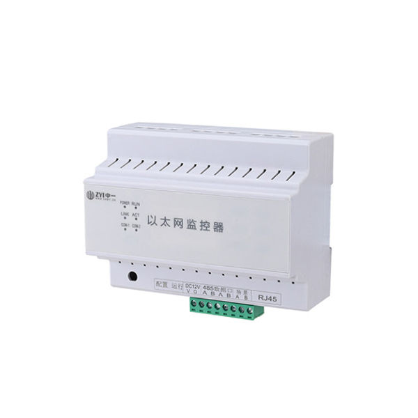
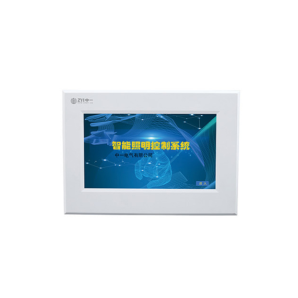
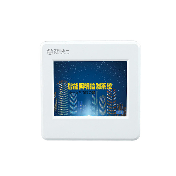
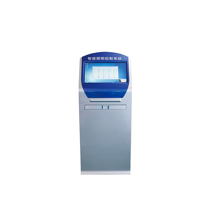
Planks, 4-inch Touchscreen, 7-inch Touchscreen, Smart Lighting Control Master Unit, Mobile App (Controller must support cloud)
Data transmission, PC endpoint, and network control.
2. Supported Protocols
CAN Protocol, 485-MODBUS Protocol, MQTT Protocol, OPC Protocol, API Protocol, TCP Protocol.
Controller and loop settings can be configured with the timing data required for your specific scenario. 5. Latitude and Longitude Control
Due to the significant variation in day and night lengths throughout the year, with latitude and longitude control activated, the system will automatically adjust the lighting and dimming times according to the season. 6. Weekly Schedule
Each circuit can be freely set to activate the automatic timing function on weekdays to Sunday. 7, Photocontrol control
Set the light switch value; the controller can issue automatic control commands based on the light intensity.
8. Fire linkage
Equipment receives an active DC24V alarm signal from fire or fire transmission, and the controller makes corresponding interlock actions. 9. Unboxing Alarm
The controller is installed with the corresponding opening box alarm sensor inside the distribution box. Upon opening, the intelligent lighting equipment will activate.
Alarm signals are transmitted to the backend.
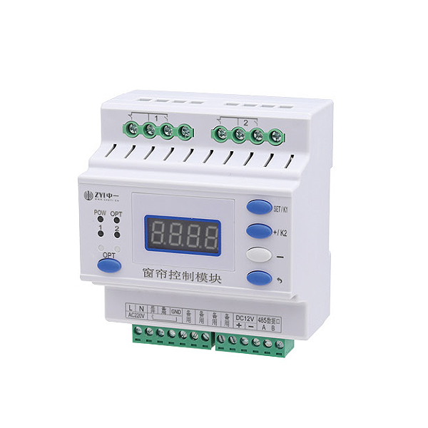
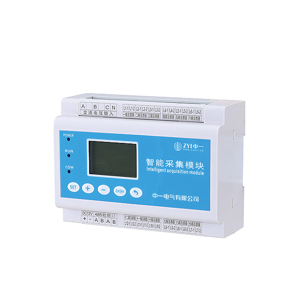
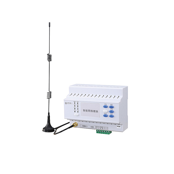
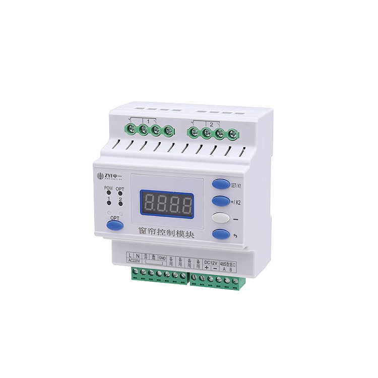
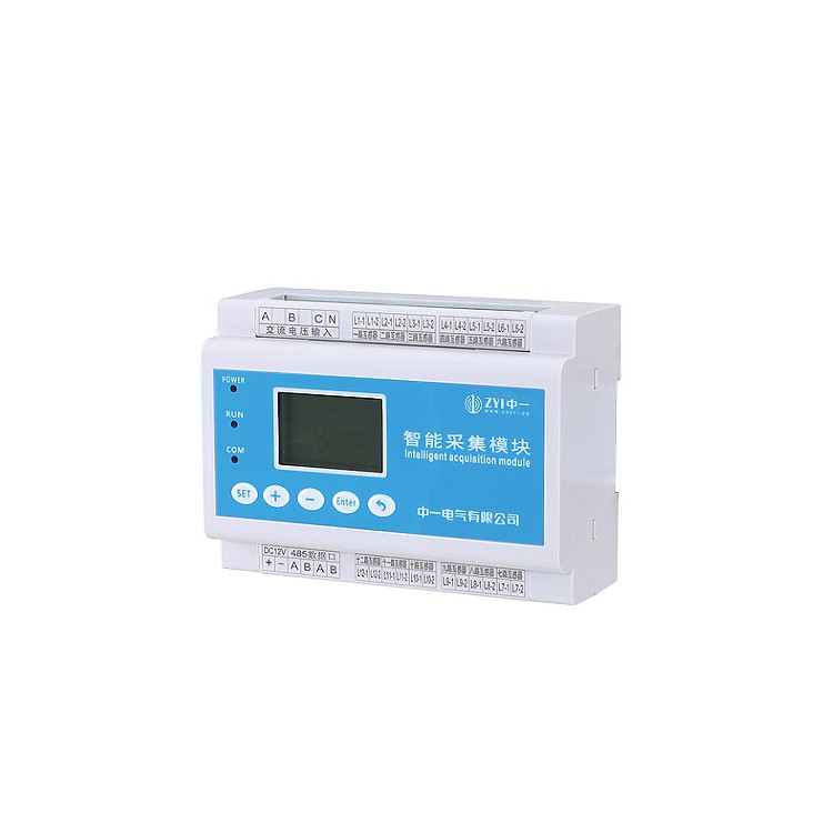
CAN Communication, RS485 Communication Interface, Four, System Composition
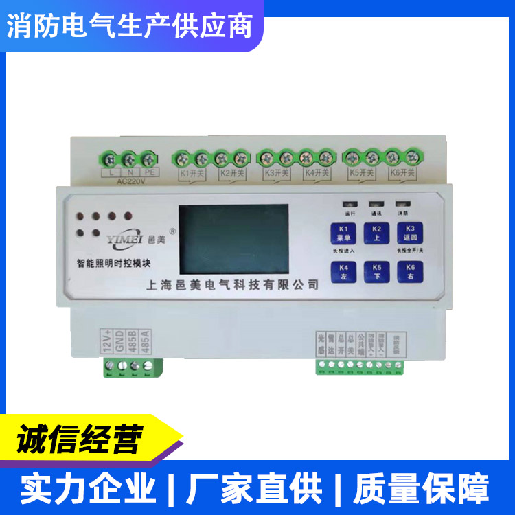
III. Parameters 1. Power Supply Voltage: Standard AC220CV, customizable from DC12V to 36V 2. Communication Interface: 3. Rated Current: 1. Simple Wiring Diagram for Distribution Box A B C N A B C N L N L N L N L N L N L N L N L N L N L N L N L N L N L N L N L N L N L N L N L N L N L N Settings Shift Data+ Data-
Save Return K1 K2 K3 K5 K6K4 Common Terminal 1 1 2 3 5 4 6 7 8 9 Feedback Output Fire Input 10 11 12 13 Rs485 CAN B A L H L N L N L N L N L N L N L N Rated Current Relay Characteristics Inductive (LED light) Resistive (incandescent light) 16A 20A 50A Electric Hold Magnet Hold Magnet Hold Hold Hold Hold Hold Hold Hold 3.5KW 4.4KW 11KW 0.5KW 1KW 3KW AC220V Power Supply
A B C N A B C N L N L N L N L N L N L N L N L N L N L N L N L N L N L N L L N N
AC 220V Input
Smart Power Supply Unit - DC12V Output - Settings - Shift - Data+ - Data-
Save Return K1 K2 K3 K5 K6 K4 Common Terminal 1 1 2 3 5 4 6 7 8 9 Feedback Output Fire Input 10 11 12 13 Rs485 CAN B A L H IANTERN 01 IANTERN 02 IANTERN 03 IANTERN 04 IANTERN 05 IANTERN 06 IANTERN 07 IANTERN 08 IANTERN 09 IANTERN 10 IANTERN 11 IANTERN 12 IANTERN 13 IANTERN 14 IANTERN 15 IANTERN 16 Communication Wire RVVSP2*1.5 2, Remote Panel Wiring Diagram Power Wire STP2*1.5
3. System Network Diagram
Set, Shift, Data+, Data-
Save Return K1 K2 K3 K5 K6K4 Common Port 1 1 2 3 5 4 6 7 8 9 Feedback Output Fire Input 10 11 12 13 Rs485 CAN B A L H Settings Shift Data+ Data-
Save Return K1 K2 K3 K5 K6K4 Common Terminal 1 1 2 3 5 4 6 7 8 9 Feedback Output Fire Input 10 11 12 13 Rs485 CAN B A L H Set Shift Data+ Data-
Save Return K1 K2 K3 K5 K6K4 Common Terminal 1 1 2 3 5 4 6 7 8 9 Feedback Output Fire Input 10 11 12 13 Rs485 CAN B A L H Set Shift Data+ Data-
Save Return K1 K2 K3 K5 K6K4 Common Terminal 1 1 2 3 5 4 6 7 8 9 Feedback Output Fire Input 10 11 12 13 Rs485 CAN B A L H Settings Shift Data+ Data-
Save Return K1 K2 K3 K5 K6K4 Common Port 1 2 3 5 4 6 7 8 9 Feedback Output Fire Input 10 11 12 13 Rs485 CAN B A L H Settings Shift Data+ Data-
Save Return K1 K2 K3 K5 K6K4 Common Terminal 1 1 2 3 5 4 6 7 8 9 Feedback Output Fire Input 10 11 12 13 Rs485 CAN B A L H Set Shift Data+ Data-
Save Return K1 K2 K3 K5 K6K4 Common Port 1 2 3 5 4 6 7 8 9 Feedback Output Fire Input 10 11 12 13 Rs485 CAN B A L H Set Shift Data+ Data-
Save Return K1 K2 K3 K5 K6K4 Common Port 1 2 3 5 4 6 7 8 9 Feedback Output Fire Input 10 11 12 13 Rs485 CAN B A L H Set Shift Data+ Data-
Save Return K1 K2 K3 K5 K6K4 Common Terminal 1 1 2 3 5 4 6 7 8 9 Feedback Output Fire Input 10 11 12 13 Rs485 CAN B A L H Set Shift Data+ Data-
Save Return K1 K2 K3 K5 K6K4 Common Port 1 1 2 3 5 4 6 7 8 9 Feedback Output Fire Input 10 11 12 13 Rs485 CAN B A L H Set Shift Data+ Data-
Save Return K1 K2 K3 K5 K6K4 Common Terminal 1 1 2 3 5 4 6 7 8 9 Feedback Output Fire Input 10 11 12 13 Rs485 CAN B A L H Set Shift Data+ Data-
Save Return K1 K2 K3 K5 K6K4 Common Terminal 1 1 2 3 5 4 6 7 8 9 Feedback Output Fire Input 10 11 12 13 Rs485 CAN B A L H AAA BBB Gateway Gateway Gateway CAT5e Cable RVVSP4*1.5 RVVSP4*1.5 RVVSP4*1.5
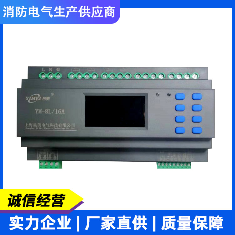
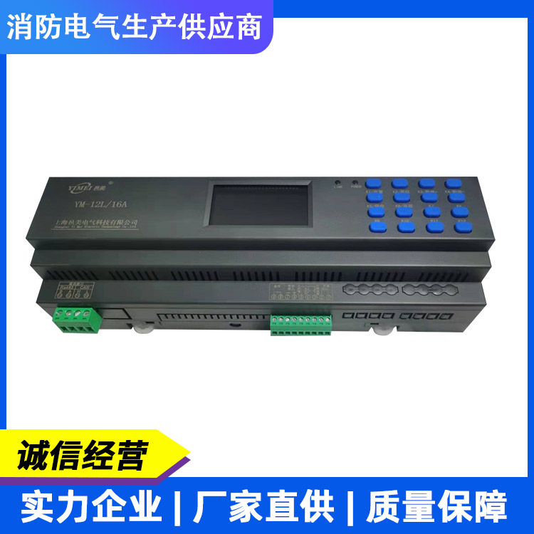
V. Function Settings 1. Interface Display - Buttons K1, K2, K3, K4, K5, K6, K7, K8, K9, K10, K11, K12, K13, K14, K15, K16 - Long press to enter setting mode, short press to toggle circuit 1 on/off - Setting mode shift key, long press to display brightness value, short press to toggle circuit 2 on/off - Setting mode data increase key, short press to toggle circuit 3 on/off - Setting mode data decrease key, short press to toggle circuit 4 on/off - Setting mode save key, short press to toggle circuit 5 on/off - Setting mode return key, short press to toggle circuit 6 on/off - Short presses to toggle circuits 7-16 on/off - Settings - Shift - Data + - Data -
Save Return K1 K2 K3 K5 K6K4 Common Port 1 1 2 3 5 4 6 7 8 9 Feedback Output Fire Input 10 11 12 13 Rs485 CAN B A L H
2. Key Definitions 01 02 03 04 Set Shift Data+ Data-
Save Return K1 K2 K3 K5 K6K4 Common Terminal 1 1 2 3 5 4 6 7 8 9 Feedback Output Fire Input 10 11 12 13 Rs485 CAN B A L Dark: Dawn:
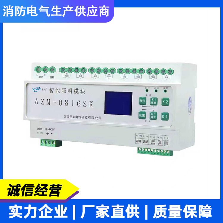
Smart Lighting Timer Controller
ID: Luminance:
: 01 02 05 06 09 10 13 14 03 04 07 08 11 12 15 16 . Weekday Year Month Day Alarm:
Digital Display, LCD Display
3. Function Settings - Address Settings - Display Codes - Setting Steps - Press and hold the set key to display - Press the set key to display - Press K2 to shift, K3 to increase data, K4 to decrease data, adjust the required address - Press K5 to save data, display - Press K6 to return to the upper menu - For Address 1 - Press and hold the set key to display - Press and hold K3 key to adjust to - Press the set key to display - Press K2 to shift, K3 to increase data, K4 to decrease data, adjust the required address - Press K5 to save data, display - Press K6 to return to the upper menu - Loop Settings - Time Settings - Press and hold the set key to display - Press K3 key to adjust to - Press the set key to display the time before setting - Press K2 to shift, K3 to increase data, K4 to decrease data, adjust the required time - Press K5 to save data, display - Press K6 to return to the upper menu - Press and hold the set key to display - Press K3 key to adjust to - Press the set key to display the cursor blinking position - For this loop, lighting represents off - Lighting represents on - Lighting represents off - Lighting represents on - Lighting represents off - Lighting represents on
Light Indicator, Time Indicator, Minute Indicator
1. Street light marker lights up for road setup. Press the set button, the numeric cursor blinks, then press set, press K2 to shift.
K3 increments data as K4 decreases, adjust the timing for turning on the lights. Press K6 to return to the shutdown settings, press K2 to shift, press K3 to increase and K4 to decrease data, adjust the timing for turning off the lights. If more time periods are set for this circuit, set them in a loop using the above method. To set the next circuit, press K2 when the cursor blinks to shift to the next circuit's indicator, and set the required timed control in sequence. If all circuits have the same on/off light time, you can only set the circuit data and save it. Then, go to the settings unit to copy circuit settings in bulk. Press K5 to save data, and press K6 to return to the upper menu for timed control settings.
Feature Settings Display Code Setup Steps Press and hold the setup key to display Press K3 key to adjust to Press the setup key to display
1. Streetlight markers illuminate road settings; press K5 to save data; press K6 to return to the upper menu; latitude and longitude
Enable, press the Set button, modify according to the following method, this value is the latitude and longitude enable value. Press K2 to shift, K3 to increase data, K4 to decrease data. Adjust the required startup value, press K6 to return, then press K2 to shift to the next circuit. The streetlight indicator lights up, and you can set the corresponding circuit startup value. Follow the same method to set more circuit latitude and longitude startup values. If all circuits have the same on/off time, you can only set the road data to save, then go to the setting unit to batch copy circuit setting data. After saving the data, you can view the on/off time values by latitude and longitude. Press the Set button, press K3/K4 to change the blinking cursor, for latitude and longitude lighting time. Latitude and Longitude
Dimming Time: This value is view-only and cannot be modified. To set the middle-of-the-night lighting mode, adjust the blinking cursor, set the lighting time, this time value is set after the latitude and longitude are activated, as the dimming time value. Before setting the latitude and longitude, calibrate the local latitude and longitude values in the settings section. Press and hold the settings button, press K3 to adjust, press the settings button to display, press K5 to save data, press K6 to return to the upper menu. Time Control Batch
Set by holding the settings key, display by pressing the K3 key to adjust to Latitude and Longitude, Year, Month, Day
Calibrate, press the set key to display, adjust "Latitude," press the set key to enter, press K2 to shift, press K3/K4 to add/subtract data, press K6 to return; press K3 data key to display.
Adjust "Longitude," press the SET key to enter, press K2 to shift, press K3/K4 to add/subtract data, press K6 to return; press K3 data key to display. Adjust "Year," press the SET key to enter, press K2 to shift, press K3/K4 to add/subtract data, press K6 to return; press K3 data key to display. Adjust "Month," press the SET key to enter, press K2 to shift, press K3/K4 to add/subtract data, press K6 to return, press K3 data key to display. Adjust "Day," press the SET key to enter, press K2 to shift, press K3/K4 to add/subtract data, press K5 to save data, press K6 to return to the upper menu.
Feature Settings Display Code Setting Steps Hold down the setting key to display Press K3 to adjust to Press the setting key to display Indicates turning on early by 00 minutes Press to display
The delay in turning on the lights is represented as 00 minutes. Press K2 to switch between advance and delay, press K3/K4 to adjust the advance or delay time, and press the set button to display.
The indicator for turning off the lights early shows "00 minutes ahead." The indicator for turning off the lights late shows "00 minutes behind." Press K2 to switch between early and late, and press K3/K4 to adjust the time ahead or behind.
Save data by pressing K5, display "Press K6 to return to the upper menu", Latitude and Longitude Compensation
Press and hold the settings key, display Press K3 key to adjust to Press settings key to display, 1 road light indicator lit represents setting back to loop, front blinking indicates Monday, press K3/K4 to switch to Tuesday.
For Wednesday, For Thursday, For Friday, For Saturday,
For Sunday, press the SET button to activate. Press K3/K4 to toggle between activation and deactivation. Press the RETURN button, then press K3/K4 to sequentially set other days. When the cursor blinks, press K2 to shift. The next loop indicator lights up. Follow the same method to set other loops and days. Weekday Mode
Set by pressing K5 to save data, press K6 to return to the upper menu. Press and hold the setup key to display, press K3 to adjust to. Press and hold the setup key to display as full-open fire联动 mode, press K3/K4 to switch to full-closed fire联动 mode. Press K5 to save data, press K6 to return to the upper menu. Press and hold the setup key to display, press K3 to adjust to. Press and hold the setup key to display as switch quantity self-lock signal, press K3/K4 to switch to switch quantity point signal. Press K5 to save data, press K6 to return to the upper menu. Fire联动
Set up
Switching Signal Settings
Feature Settings Display Code Setup Steps Hold down the setup key, display Press K3 key to adjust to Hold down the setup key, display for each relay circuit to open and close with a delay of 100 milliseconds, can be shifted with K2, adjusted with K3/K4, adjustment range 100-1000 milliseconds. Press K5 to save data, display Press K6 to return to the upper menu
Drive Delay
Press and hold the settings key, display Press K3 key to adjust to Press the settings key, display Baud rate is 9600bps, press K3/K4 keys to switch
Swap (2400 bps) (4800 bps) (14400 bps)
(19200 bps) (115200 bps) Save data with K5, Display K6 to Return to Previous Menu
Port rate
Set by holding the Setup key, display Press K3 to adjust to Light Sensitivity setting Press K5 to save data, display Press K6 to return to the upper menu Hold the Setup key, display Press K3 to adjust to Press the Setup key, toggle with K3/K4 (Off) (On) Press K5 to save data, display Press K6 to return to the upper menu Hold the Setup key, display Press K3 to adjust to Press the Setup key, display Press K5 to save data, display Press K6 to return to the upper menu Unboxing Alarm
Set / Restore to Factory Settings
Set - Press the Set button, display indicates the switch setting value. The device automatically determines the on/off switch value. For example: if the setting value is 50, the device judges the on-value for lighting to be 44 and the off-value to be 56. The setting value can be adjusted by pressing K3/K4. Pressing Set 1 lights up the road lamp indicator, display indicates the road light sensor is in the off state. Pressing K3/K4 can switch to indicate the on state. Pressing Set can switch to the next circuit setting.
6. Installation Dimensions 7. Precautions
Properly use the equipment's power supply.
One-year product warranty.
Power Usage
2. Maintenance and Replacement
3. Product Storage: No person shall open or maintain the central controller without the consent of our company.
Repaired, in accordance with the National Standard GB 13955-2005, the service life of this device is six years, at which time it should be...
For replacement. The storage area should be clean and dry, with an environmental temperature of -40 to 85°C, and relative humidity not exceeding
85, and free from harmful substances capable of causing corrosion in air.
The product should not be subjected to severe impact during transportation and unpacking, and should comply with GB/T1546-1995 "Instruments - General safety requirements for the design and construction of instruments and their accessories."
Regulations for transportation as specified in the "Table of Packaging and Transportation Technical Conditions."
4. Product Transportation Settings: Move Data + Data -
Save Return K1 K2 K3 K5 K6 K4 Common Terminal 1 1 2 3 5 4 6 7 8 9 Feedback Output Fire Input 10 11 12 13 Rs485 CAN B A L H A B D C EH G F 4 Circuits Specifications A (Length) 108mm 180mm 180mm 252mm 252mm 6 Circuits 8 Circuits 12 Circuits 16 Circuits B (Width) 95mm 95mm 95mm 95mm 95mm C (Height) 68mm 68mm 68mm 68mm 68mm D 65mm 65mm 65mm 65mm 65mm E 45mm 45mm 45mm 45mm 45mm H 35mm 35mm 35mm 35mm 35mm F 40mm 40mm 40mm 40mm 40mm G 16mm 16mm 16mm 16mm 16mm
Section 8: Product Warranty Warranty Card Information (filled out by the user) User Unit Contact Phone Number Communication Address Purchase Store Product Name Product Model Purchase Date Usage Item Fault Description Factory Repair (filled out by the repair personnel) Repair Date Method of Handling 1 Fault Content 1 Repair Unit Fault Content 2 Repair Personnel Signature Method of Handling 2 Fault Content 3 Method of Handling 3 Contact Phone Number


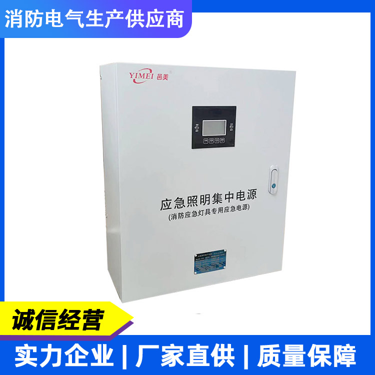
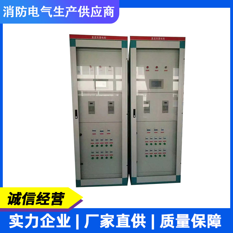
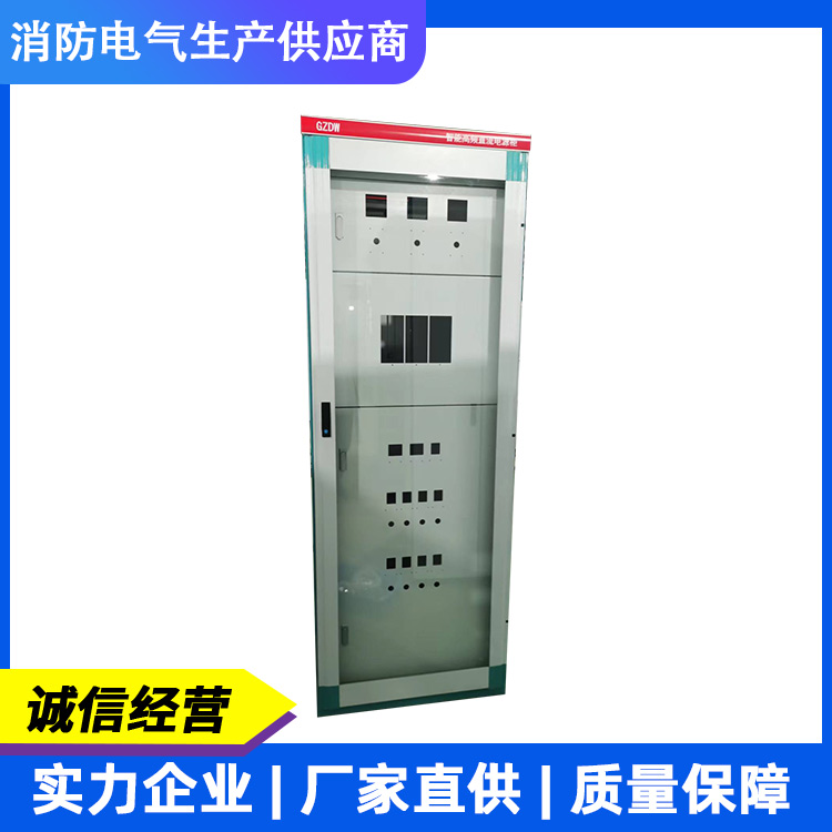
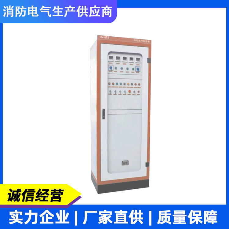
Yimei Electrical Technology is a high-tech company engaged in the research, development, production, and sales of power equipment products. Our main products include uninterruptible power supplies (UPS), emergency power supplies (EPS), DC screens, fire patrol cabinets, intelligent fire evacuation systems, fire monitoring power supplies, and other intelligent, energy-saving, and environmentally friendly products. Our products are widely used for emergency lighting in large high-rise buildings, airports, office buildings, shopping malls, schools, squares, stations, parks, factories, sports venues, and exhibition centers. They also serve as emergency power supplies for important areas such as elevators, water pumps, fans, rolling shutters, and other fire protection power equipment. We can design products according to customer requirements to meet their needs in various environments.
Market-oriented, we continuously enhance new product development efforts and consistently establish and refine sales service networks across the country, providing users with timely technical support and ample spare parts, earning widespread praise.
Yi Mei Electrical Technology's entire staff warmly welcomes visitors from all over the country to visit our company for inspection and guidance, and to jointly create a brighter future! We warmly invite all ambitious individuals to join our ranks!