


FSB Type Fluoroplastic Centrifugal Pump Image & Fluoroplastic Centrifugal Pump Structural Diagram
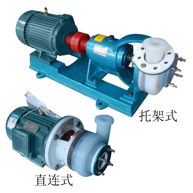
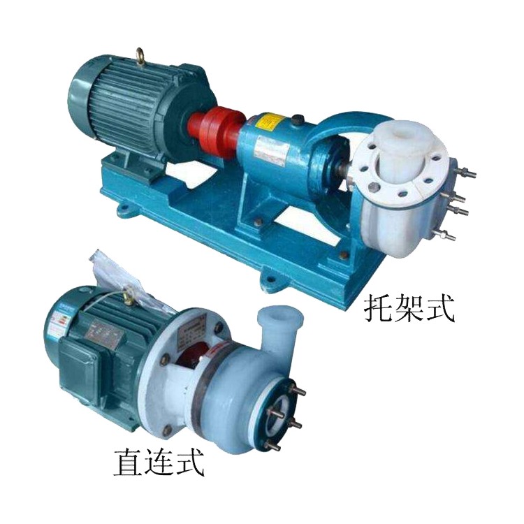
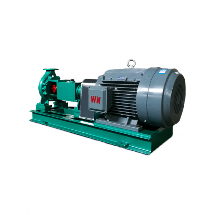
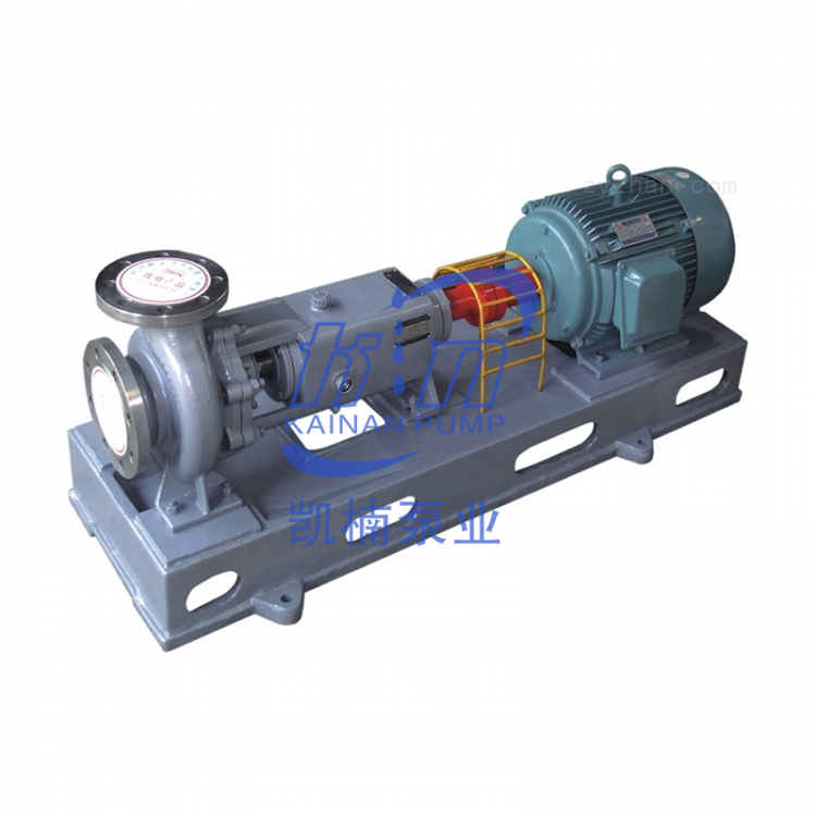
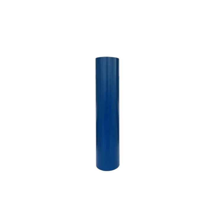
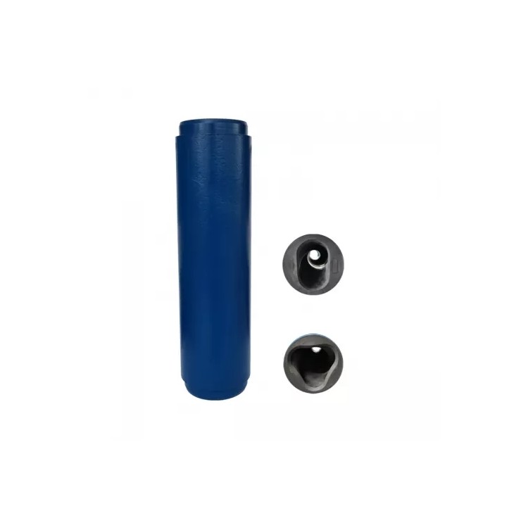
1. Image of Fluoroplastic Centrifugal Pump

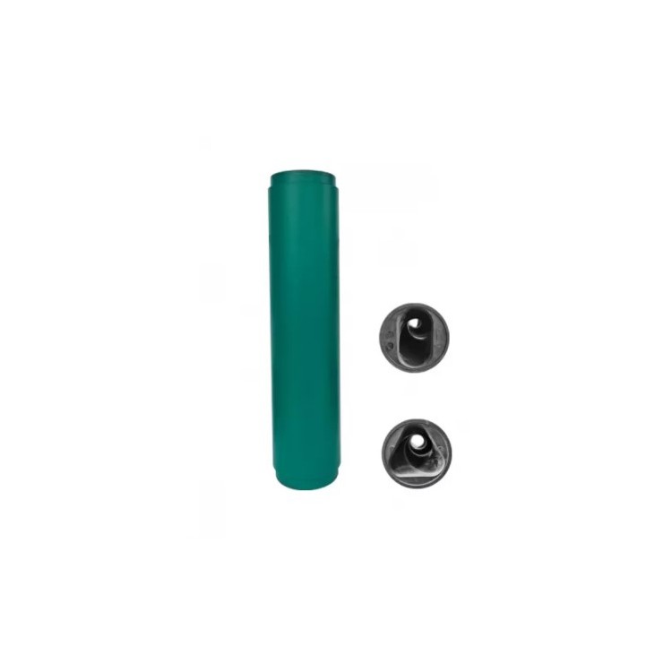
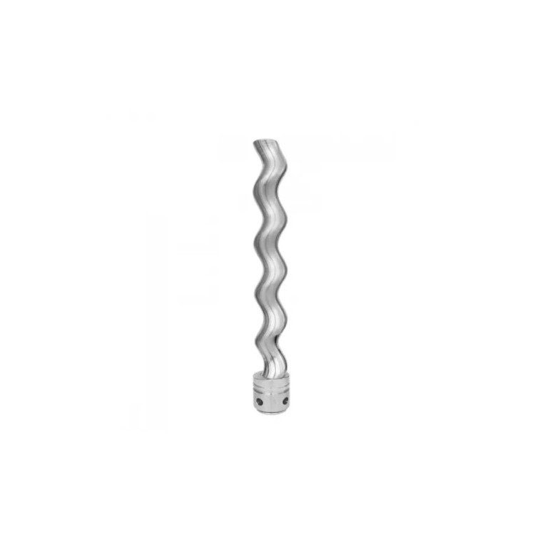
2. Fluoroplastic Centrifugal Pump Structural Diagram

FSB Fluoroplastic Centrifugal Pump Model Explanation
50FSB-30D
50: Inlet Diameter mm
F: Corrosion-resistant series,
Centrifugal
30: Head pressure
Direct-Connected Fluoropolymer Alloy Pump (If L denotes a Fluoropolymer Alloy Pump with a Coupling)
FSB Fluoroplastic Centrifugal Pump performance parameters, please contact our sales staff.
FSB Pumps: Installation, Usage, and Precautions
Before installation, inspect the pump and motor; all parts should be intact and damage-free, with no foreign objects inside the pump.
2. Place the pump horizontally, connect the inlet and outlet pipes, and power it on. Then manually rotate the coupling. Check for any rubbing or scraping. If the rotation is smooth and even, the installation is complete.
3. Plastic alloy pump steel has lower rigidity than metal, therefore, the pipeline weight cannot be directly pressed onto the pump body.
The outlet pipeline should be supported by additional brackets. For pumps with high lift, a check valve should also be installed at the outlet to prevent water hammer damage due to sudden shutdown.
All joints must remain sealed to prevent air or liquid leaks that could affect the pump's performance.
5. If any movement or abnormal sounds are detected during operation, the machine should be stopped immediately to investigate the cause. The machine can only resume work after the issue is resolved and the cause is excluded.