


Ⅰ. Insertion Type Vortex Flow Meter Flow Range
Ⅱ. Product Selection

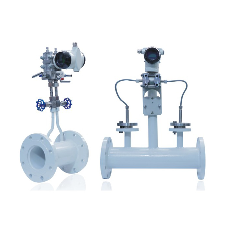
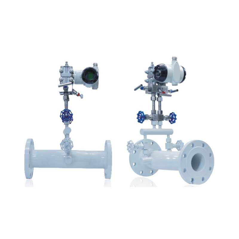
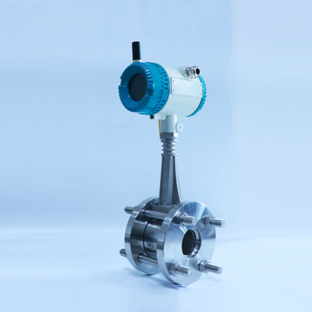
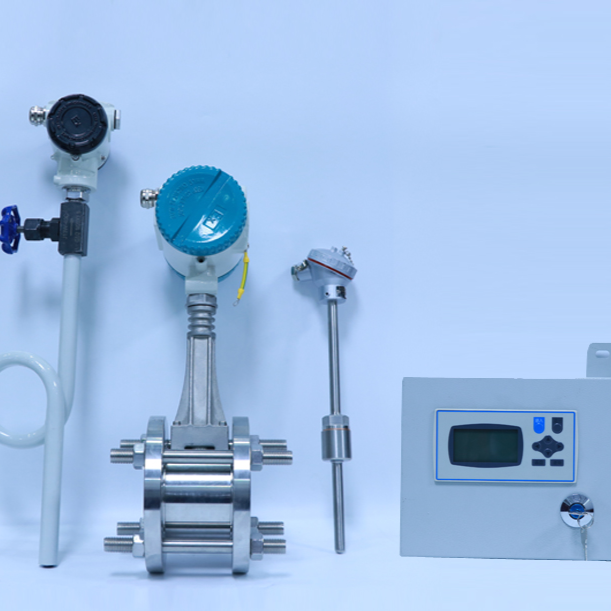
III. Installation and Dimensions of Insert Type Vortex Flow Meters
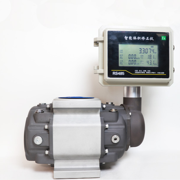
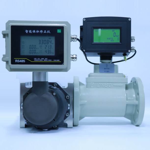
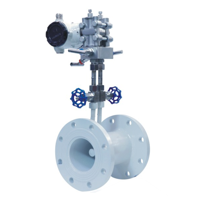
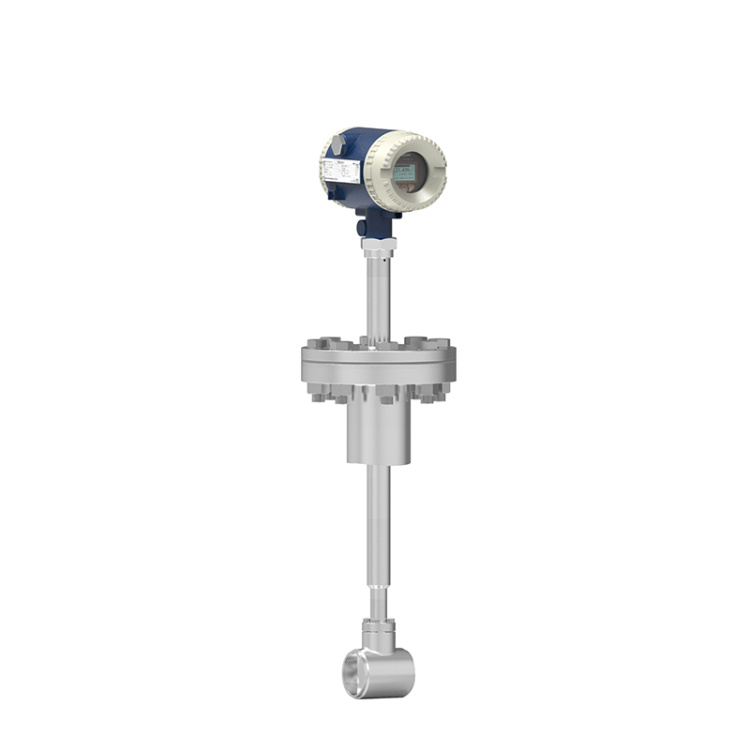
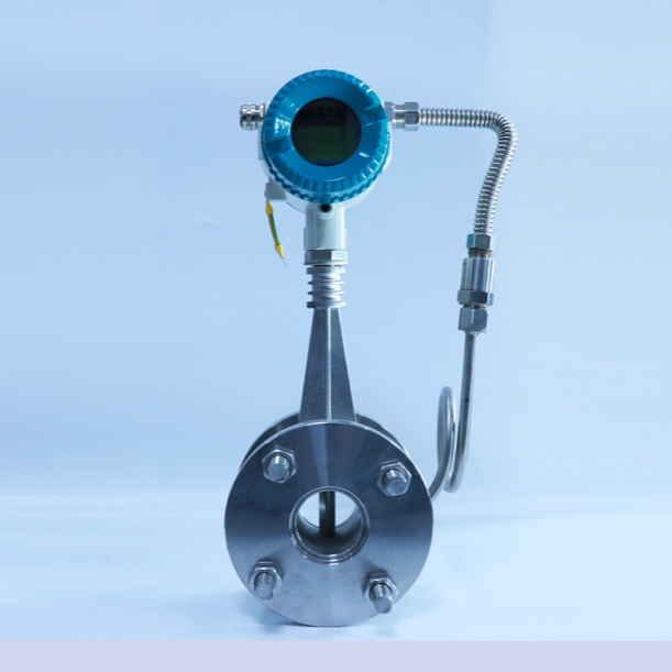
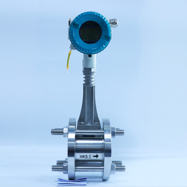
1. Structural Form
2. Simple Flow Meter Installation Method
Cut a circular notch of Φ100 at the installation point meeting the straight section requirements of the flowmeter.
■Weld the lower tube section with a base of Ф109 x 4.5mm to the pipe's pre-cut circular notch, ensuring no noticeable misalignment upon visual inspection after the base welding.
Insert the speed probe into the pipe, adjust the insertion depth to align the probe's center with the pipe's axis, ensuring the angle between the probe's centerline and the pipe's axis is no more than 5 degrees. Then, adjust the flow indicator to match the direction of the fluid flow.
Align the flange or ball valve with the焊接 base and securely tighten with bolts.