


Ⅰ. Product Features
High precision, excellent repeatability, wide range ratio up to 1:20 (or wider).
■ Utilizing an integrated new rectifier, the requirements for the straight pipe sections are lower (front ≥ 25DN, rear ≥ 3DN).
Utilizing a uniquely designed dustproof structure, ensuring the reliability of long-term bearing operation.
The design features a unique fueling system, ensuring reliable fueling, easy maintenance, and a stylish appearance.
Technical specifications meet the requirements of ISO 9951-1993 standard, with the table length of 3DN, the whole machine reaches an internationally advanced level.
The flow meter's volume corrector can rotate freely about 350°, allowing for easy reading in various installation orientations.
Low RPM, high lifespan, low pressure loss, high precision;
Integrating high-precision temperature, pressure, flow sensors, and volume correction instruments, this device can detect the temperature, pressure, and flow of the measured gas, and perform automatic flow tracking compensation and compression factor correction calculations. It features an onboard real-time database, facilitating centralized data collection and real-time management via RS485 communication interface and meter reading network.
■ Utilizing high-performance microprocessors and modern digital filtering technology, the software boasts powerful functionality and superior performance.
■ Utilizes floating-point arithmetic and automatic correction with five-section meter coefficients, featuring fault self-diagnosis and alarm functions.
■ Utilizing micro-power high-tech, powered by both internal and external power sources, the overall power consumption is low.
Locally display flow values and come with various signal output functions.
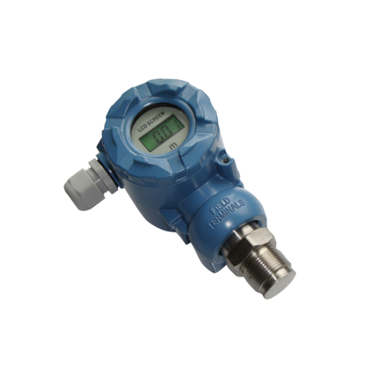
■ Equipped with a high-contrast three-line LCD display, it can show standard cumulative flow, standard volume flow, operating volume flow, medium temperature, pressure values, and battery capacity percentage, with Chinese prompt symbols.
Real-time data storage capability ensures data is not lost during battery replacement or sudden power outages; internal parameters are continuously preserved even during power cuts.
The instrument features explosion-proof capabilities, with the explosion-proof marking of ExdIICT6.
II. Operating Principle
As fluid passes through the flowmeter, it is streamlined and accelerated by the leading fluid (or a straightener). Due to the blades' angle with the fluid flow direction, the turbine generates a rotational torque. After overcoming the friction torque and fluid resistance torque, the turbine begins to rotate. Within a certain flow range, the angular velocity of the turbine's rotation is proportional to the fluid volume flow rate. According to the principle of electromagnetic induction, a magnetic sensor detects a pulse signal proportional to the fluid volume flow rate from the synchronous rotating sender disk. This signal is sent to the volume corrector, where it is processed along with signals like temperature and pressure, and then displayed on the LCD screen. The structural principle is shown in Figure 1.
4.2 Principle of Volume Correction Instrument
The volume corrector is composed of temperature and pressure detection analog channels, flow detection digital channels, a microprocessor unit, liquid crystal drive circuit, and other auxiliary circuits. It is equipped with an external signal interface. The multi-channel signals from various sensors are converted and processed by the microprocessor, which then applies the gas equation for formula calculations, achieving on-site display and various types of signal remote transmission.
Ⅲ. Product Categories
The LWGQ series gas turbine flowmeters, categorized by instrument function, are divided into two main types: 1. LWGQ type gas turbine flowmeter, 2. LWGZ type gas turbine flowmeter.
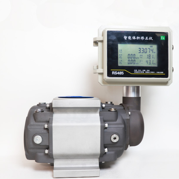
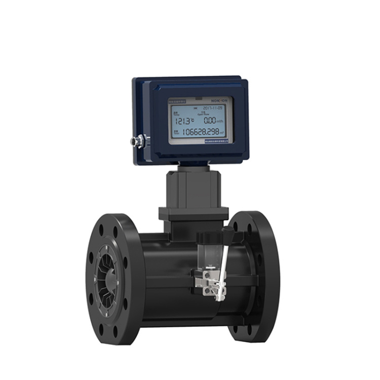
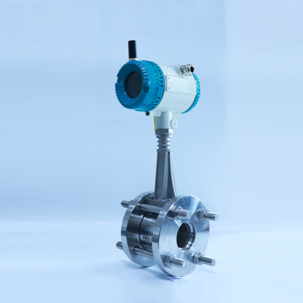
LWGQ Type Gas Turbine Flow Meter
(1) Product Overview
The LWGQ type gas turbine flowmeter integrates a turbine flow sensor and a flow totalizer.
Measurable for gas temperature, pressure, operating condition flow rate, standard condition flow rate, and total volume; suitable for gas flow and volume measurement and detection in industries such as oil, chemical, power, and metallurgy.
(2) Product Features
Integrated flow sensor and volume corrector, automatically tracks and corrects measured gas temperature, pressure, and compression factor, directly detects or measures the standard volume flow rate and total volume of the gas.
Utilizing imported precision bearings for instruments, with high accuracy and excellent stability.
Precision-engineered channel structure prevents airflow between bearings, enhancing the medium adaptability of the turbine flowmeter.
Unique reverse thrust and sealed structure design ensure long-term reliable operation of the bearing.
Utilizing magnetic reluctance sensors with high sensitivity, excellent reliability, and low start-up flow.
Self-contained core design with good interchangeability and easy maintenance.
Design rectifiers with excellent rectifying performance; the requirements for the front and rear straight pipe sections are minimal.
Network communication system is formed through RS-485 communication interface, facilitating automated management. The RS-485 communication protocol conforms to MODBUS standards.
The calibration tool can rotate 350° freely, and it is easy to install.
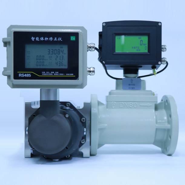
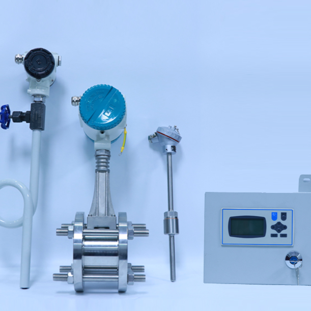
2. LWGZ Type Gas Turbine Flow Meter

Product Overview
The LWGZ-type gas turbine flowmeter integrates a gas turbine flow sensor and an electronic volume correction instrument, capable of detecting and displaying working condition flow rate and total volume. It boasts advanced technical performance domestically and conforms to GB/T18940/ISO9951 standards. It is widely used in gas measurement and detection for industries such as steam and compressed air.
Section IV: Product Selection
V. Dimensions
The flow meter dimensions are as shown in Figures 3 and 4. Dimensions not marked in the figures are listed in Table 3. The flow meter uses a flange connection method.


VI. Installation
◇ No strong external magnetic fields or intense mechanical vibrations should be present around the flow meter. Before installation, the usage environment should be reviewed according to its requirements to ensure normal operation.
Flowmeters are not suitable for applications where flow varies frequently or in situations with strong pulsating flow or pressure fluctuations.
◇When installing a flow meter outdoors, there should be a covering on top to prevent rainwater from seeping in and direct sunlight from damaging the flow meter's lifespan.
The flow meter is suitable for horizontal installation, with the fluid flow direction consistent with the direction marked on the housing; in addition, there should be straight pipe sections of 5DN and 3DN respectively upstream and downstream of the flow meter.
◇ To ensure normal fluid conveyance, bypass piping as shown in Figure 5 can be installed. The bypass pipeline valves must be closed during normal operation.
◇A filter of the corresponding specification must be installed upstream of the flowmeter (25DN), and our company can provide the matching filter.
When installing flow meters and measuring pipes, consider installing expansion joints or bellows, and lay out the upstream and downstream pipes reasonably according to the actual dimensions of the flow meter to minimize the deformation of the flow meter caused by pipeline stresses.
The flow meter should be installed coaxially with the pipeline and prevent the sealant washer and grease from entering the inner cavity of the pipeline.
◇Flowmeters must be reliably grounded according to instructions, but not share a ground wire with the high-voltage power system; during pipeline installation or maintenance, do not connect the grounding wire of the welding system to the flowmeter.
During use, users are not permitted to alter the connection methods of the explosion-proof system or make any modifications. All wire terminals should be operated strictly in accordance with the relevant requirements of GB3836.12 when necessary.
◇When the flowmeter is put into operation, the valve should be slowly opened (the opening time should not be less than 15 seconds) and the flow rate should be gradually increased to prevent the sudden airflow impact from damaging the turbine.