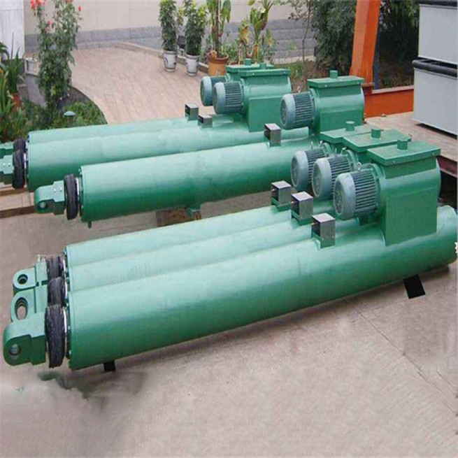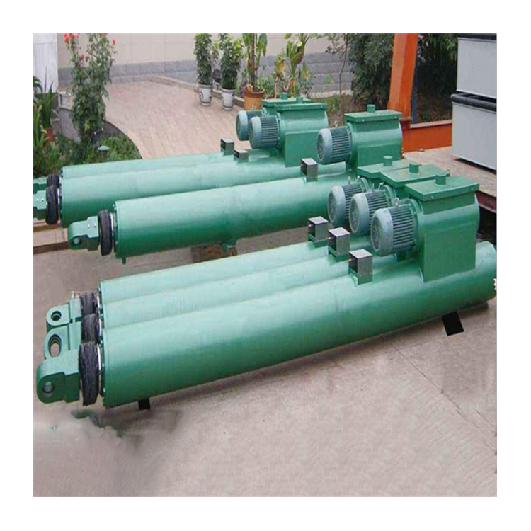


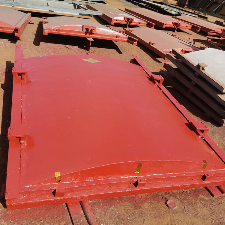
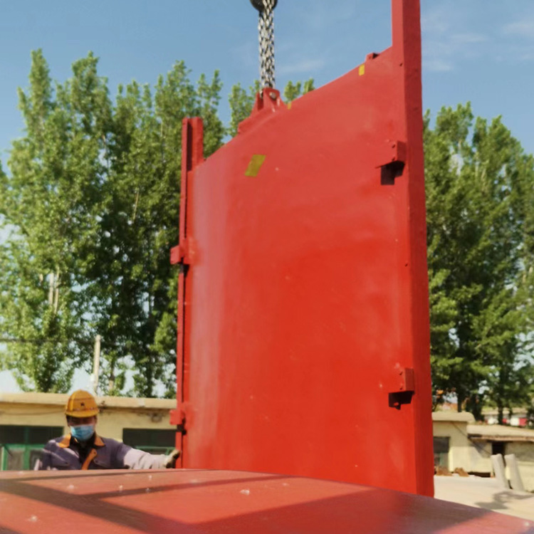


Hydraulic actuators typically consist of a hydraulic system and a hydraulic cylinder. Under the control of the hydraulic system, the inner wall of the piston within the cylinder performs reciprocating axial motion, thereby driving the connecting rod and gate attached to the piston to move in a straight line, achieving the purpose of opening and closing the orifice.
Composition Structure
The hydraulic system includes power units, control and regulation devices, auxiliary equipment, etc. Multiple gates can share a single hydraulic system.
Working Principle
The power unit is typically a hydraulic pump, which converts mechanical energy into hydraulic energy. Hydraulic pumps usually employ volumetric pumps, such as vane pumps and plunger pumps. Vane pumps and plunger pumps offer advantages like compact structure, smooth operation, low noise, and long service life. Although plunger pumps are more expensive, they provide high pressure, high flow rates, and adjustable flow. In recent years, domestic hydraulic gates commonly use medium to high pressure, so most opt for plunger pumps. Additionally, due to their importance, the hydraulic systems of hydraulic gates usually include two hydraulic pumps as backups. [1]
Control Device
The control and regulating device refers to the hydraulic control valve assembly, including throttle valves, directional valves, and relief valves, among others. These valves individually control and regulate the flow, direction, and pressure of hydraulic oil, thereby meeting various performance requirements of the hydraulic system. Most hydraulic control valves on the opening and closing machine are standard components and commonly utilize plug-in technology. Plug-in valves offer strong assembly functions, high integration, low noise, good sealing, compact structure, and global maintenance advantages. By selecting different structures and forms of pilot control valves, control covers, and integrated blocks in combination with plug-in components, one can obtain plug-in valve assemblies with functions such as directional control, pressure adjustment, and speed regulation. Since hydraulic opening and closing machines with double suspension points cannot use mechanical synchronization like winch-type machines, the control valve assembly must consider synchronization measures.
Auxiliary Equipment
Auxiliary equipment includes fuel tanks, oil pipes, pipe connectors, pressure gauges, oil filters, etc. The fuel tank is used for storing oil and dissipating heat, as well as settling impurities in the oil and separating air and moisture from the oil. The oil pipes and pipe connectors connect the power unit, regulating control unit, and hydraulic cylinders to form a complete hydraulic circuit. Impurities in the hydraulic oil can cause wear on moving parts, increase leakage, and reduce the lifespan of components, and even block valve groups, affecting the operation of the hydraulic system. It is essential to set up an oil filter to filter the hydraulic oil.
Categorized by hydraulic cylinders
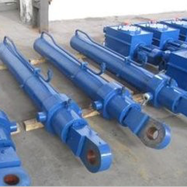
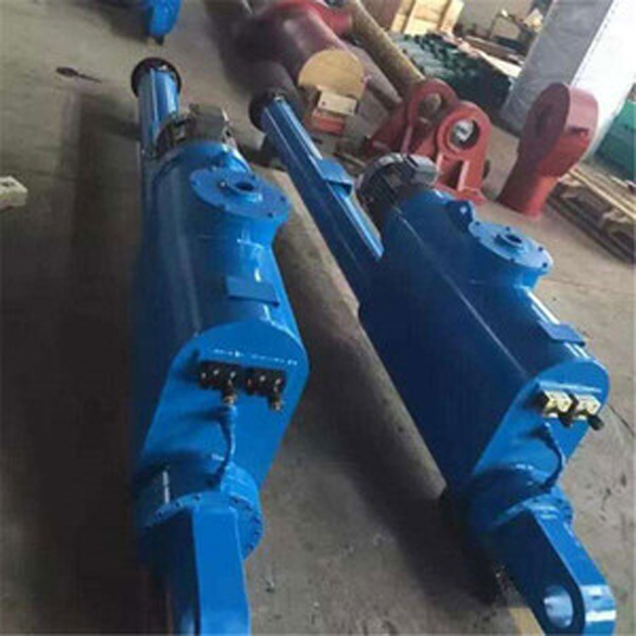
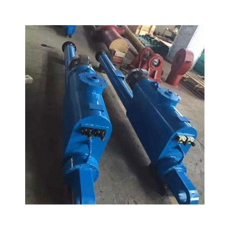
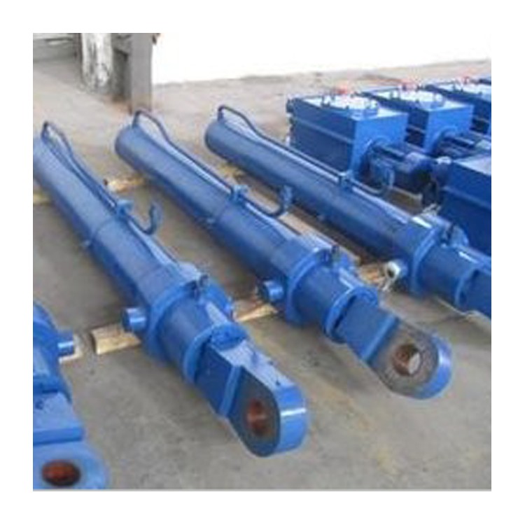
Hydraulic cylinders are the actuating elements in hydraulic power transmission, converting hydraulic energy of hydraulic oil into mechanical energy. They consist of components such as the cylinder body, end caps, piston, piston rod, and lifting head. They can be categorized into single-acting and double-acting hydraulic cylinders based on the direction of the pressure oil acting inside. Single-acting hydraulic cylinders are often plunger or sleeve type, but can also be piston type. Double-acting hydraulic cylinders have two chambers, both of which can intake and expel pressure oil.
Maintenance and care
After hydraulic system tuning, replace the oil in the tank. Change the oil after the first six months of use, and then every year thereafter. Clean the interior of the tank each time the oil is changed to ensure the normal operation of the hydraulic system; regularly clean all oil filter elements, and replace them if they are severely clogged or damaged.