


Ultrasonic flaw detector standard test block
National standard ultrasonic test block◆ National standard ultrasonic test block ◆ Professional standard ultrasonic test block ◆ Industry standard ultrasonic test block ◆ Ultrasonic testing standard test block for welding seams of building steel structures ◆ Ultrasonic testing standard test block for welding seams of normal pressure steel oil pipes ◆ Ultrasonic testing standard test block for welding seams of normal pressure steel oil pipes ◆ Ultrasonic testing standard test block for railway department ◆ Ultrasonic testing standard test block for water and electricity department ◆ Ultrasonic testing standard test block for power industry ◆ Ultrasonic testing standard test block for oil and gas industry ◆ Ultrasonic testing standard test block for aviation industry ◆ Ultrasonic testing test block for butt welds of T-shaped joints of industrial boilers ◆ Ultrasonic testing standard test block for ship industry ◆ Ultrasonic testing standard test block for welding seams of building industry ◆ Ultrasonic testing standard test block for ultrasonic testing of A3 standard in the United States ◆ Ultrasonic testing test block for ultrasonic testing of A3 standard in the United Kingdom ◆ JIS-STB-A1 in Japan Standard Ultrasonic Testing Blocks ◆ Harbin Boiler Standard Ultrasonic Testing Blocks ◆ Crane Ultrasonic Testing Blocks ◆ Rail Weld Ultrasonic Testing Blocks ◆ American Petroleum Institute API Standard Ultrasonic Testing Blocks
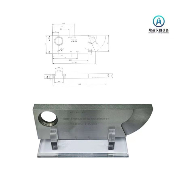
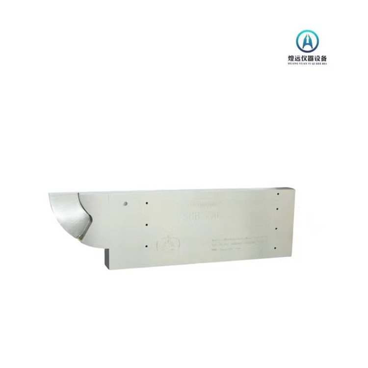
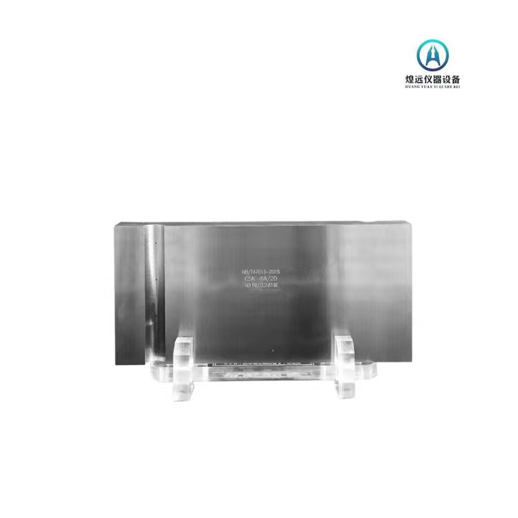
The CSK-IA test block is an improved version of the IIW test block
The main uses are:
1. Use R100mm curved surface to measure the incident point and leading edge length of the oblique probe;
2. Use 50 and 1.5mm circular holes to measure the refractive angle of the angle probe;
3. Use the right angled edge of the test block to measure the deviation of the sound beam axis of the oblique probe;
4. Use a 25mm thickness to measure the horizontal linearity, vertical linearity, and dynamic range of the flaw detector;
Adjust the longitudinal wave detection range and scanning speed using a thickness of 25mm;
6. Use R50 and R100mm curved surfaces to adjust the transverse wave detection range and scanning speed;
Measure the resolution of the angle probe using three step holes of 50, 44, and 40mm.