


I. Overview
Our country's economic development started relatively late, but has grown rapidly, resulting in many cities' road facilities not keeping up with the pace of society
The pace of development, many urban lighting systems still use old methods, and their system models have significant drawbacks
High energy consumption, requiring professional electricians for management positions, inconvenient line maintenance, and weak variability of control systems
There are issues such as significant lighting errors.
Intelligent lighting control devices are designed for various lighting application scenarios both domestically and internationally. With the continuous progress of society
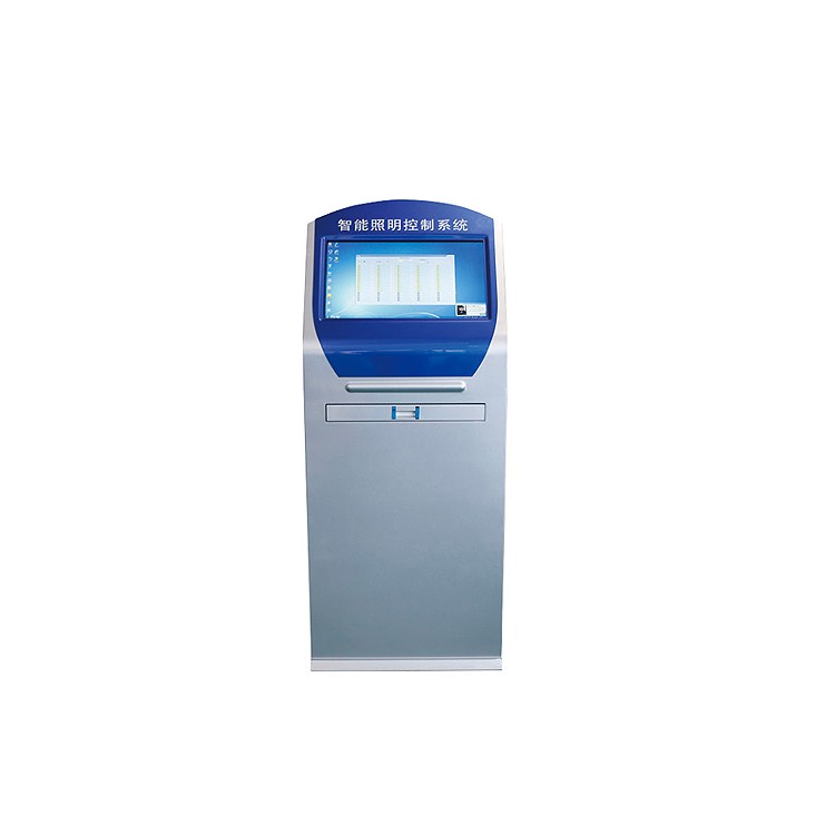
With the continuous development of urban road construction, lighting control systems are gradually achieving intelligent management. As the main lighting system for urban transportation roads, landscapes, shopping malls, airports, military bases, hotels, residential areas, gas stations, etc., it plays an important role in the construction of urban infrastructure. 2、 Function
1. Manual control
Click the control panel button to manually control each circuit and display the circuit switch status in real-time. 2. Remote control
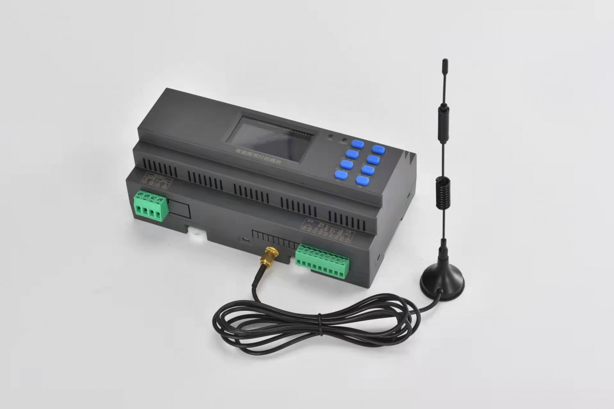
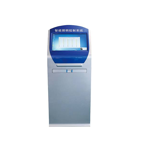
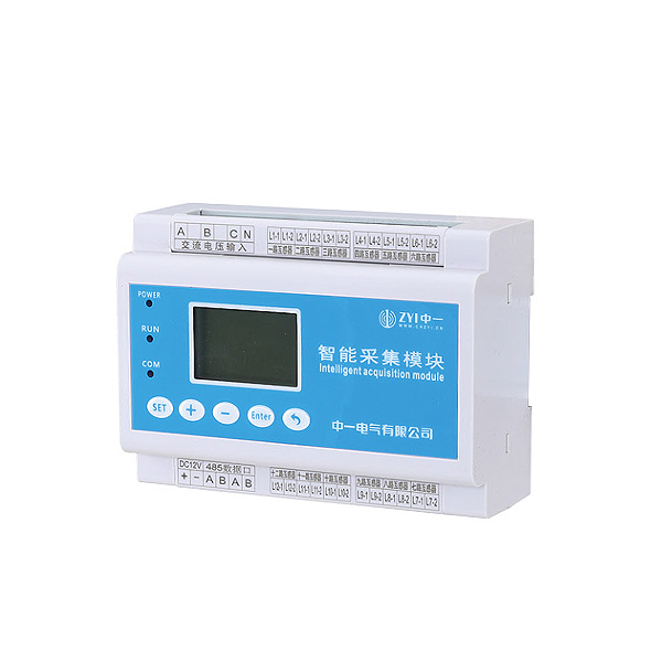
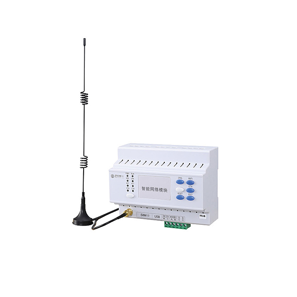
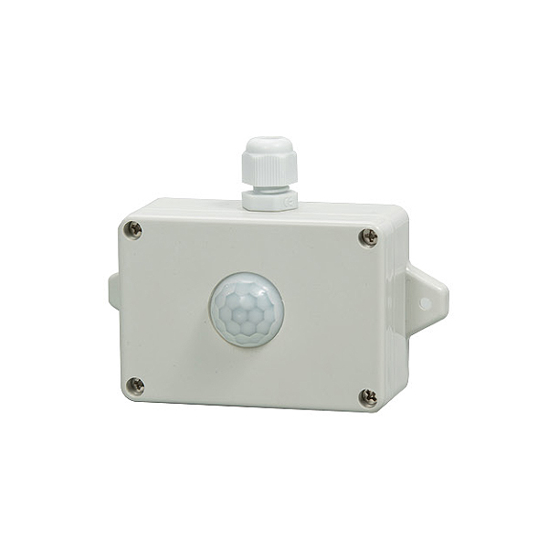
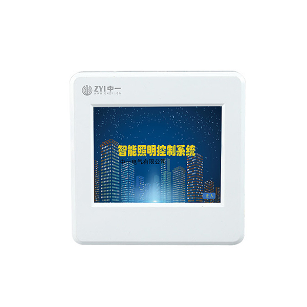
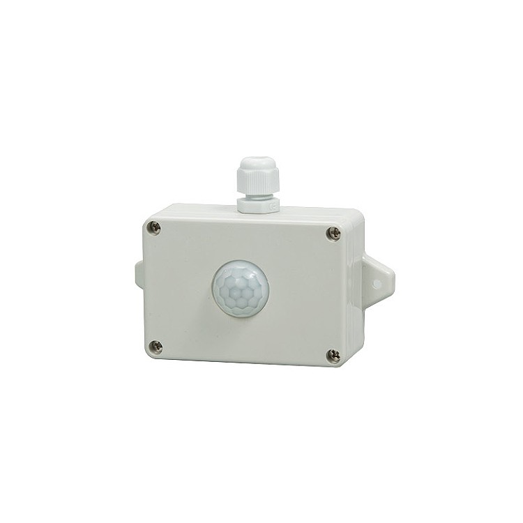
Can be achieved through infrared sensors (customized interface), microwave sensors (customized interface), optical sensors, and 86 surface sensors
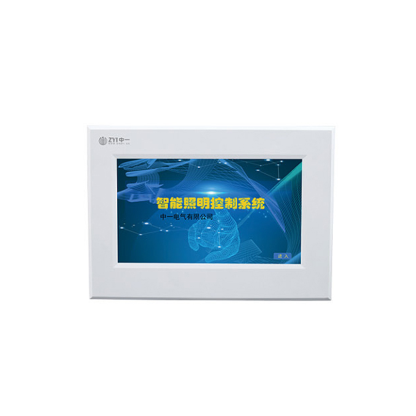
Board, 4-inch touch screen, 7-inch touch screen, intelligent lighting centralized control host, mobile terminal (controller needs to support cloud computing)
Data transmission, networking control on computer and PC terminals, etc.
2. Support agreement
CAN protocol, 485-MODBUS protocol, MQTT protocol, OPC protocol, API protocol, TCP protocol.
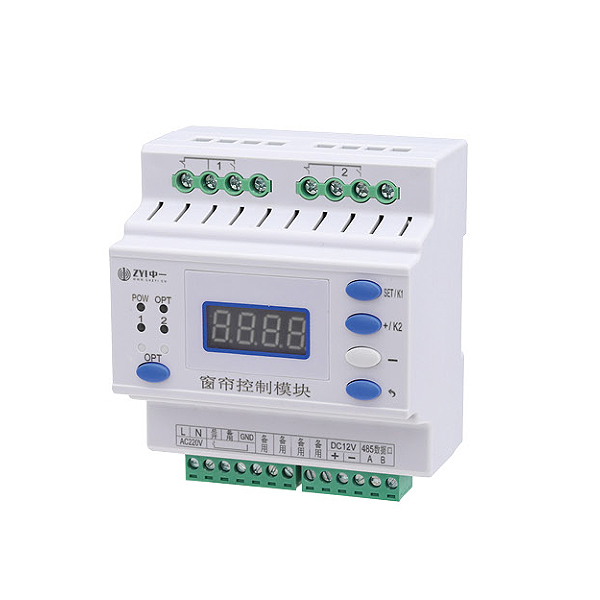
The controller and circuit can set their own timing data according to the scene they need. 5. Latitude and longitude control
Due to the significant time difference between dark and light throughout the year, when latitude and longitude control is enabled, the system will automatically adjust the on/off time of the lights based on seasonal changes. 6. Week mode
Each circuit can freely set whether to activate the automatic timing function from Sunday to Sunday. 7. Light control control
Set the light switch value and issue automatic control commands to the controller based on the light intensity.
8. Fire linkage
The device receives an active DC24V signal for fire alarm or fire protection transmission, and the controller makes corresponding linkage. 9. Unpacking alarm
The controller is installed with corresponding unboxing alarm sensors in the distribution box, and the intelligent lighting equipment will emit an alarm when unboxing
The alarm signal is transmitted to the backend.
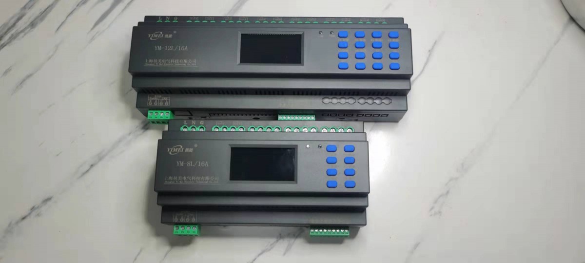
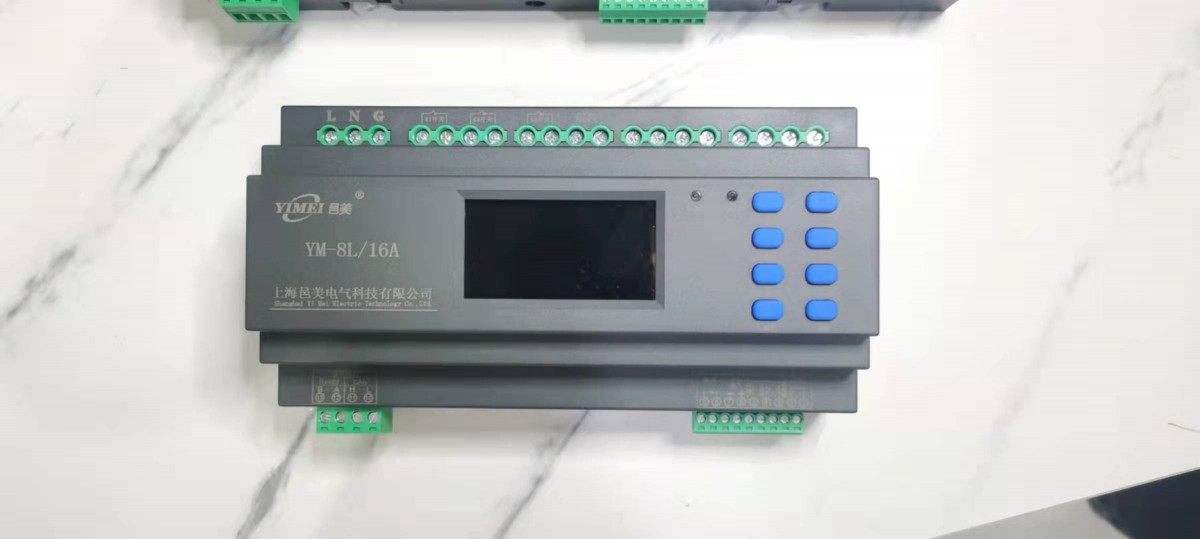
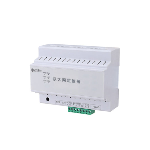
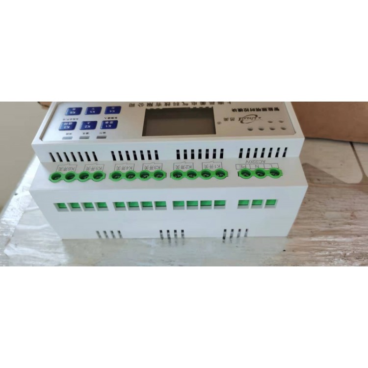
CAN communication, RS485 communication interface 4, system composition
3、 Parameter 1: Power supply voltage: conventional AC220CV, customizable DC12V~36V 2. Communication interface: 3. Rated current: 1. Simple wiring diagram of distribution box A B C N A B C N L N L N L N L N L N L N L N L N L N L N L N L N L N L N L N L N L N L N Set shift data+data-
Save and return K1 K2 K3K5 K6K4 Common terminal 1 1 2 3 5 4 6 7 8 9 Feedback output Fire input 10 11 12 13Rs485 CAN B A L H L N L N L N L N L N L N N L N Rated current Relay characteristics Inductive (LED light) Resistive (incandescent light) 16A 20A 50A Electric holding magnetic holding 3.5KW 4.4KW 11KW 0.5KW 1KW 3KW AC220V power supply
A B C N A B C N L N L N L N L N L N L N L N L N L N L N L N L N L N L N L L N N
AC220V input++--
Intelligent power supply DC12V output setting shift data+data-
Save and return K1 K2 K3K5 K6K4 public terminal 1 1 2 3 5 4 6 7 8 9 feedback output fire input 10 11 12 13 Rs485 CAN B A L H IANTERN 01 IANTERN 02 IANTERN 03 IANTERN 04 IANTERN 05 IANTERN 06 IANTERN 07 IANTERN 08 IANTERN 09 IANTERN 10 IANTERN 11 IANTERN 12 IANTERN 13 IANTERN 14 IANTERN 15 IANTERN 16 Communication line RVVSP2 * 1.5 2, remote panel wiring diagram power line STP2 * 1.5
3. System networking diagram
Set shift data+data-
Save and return K1 K2 K3K5 K6K4 public terminal 1 1 2 3 5 4 6 7 8 9 feedback output fire input 10 11 12 13Rs485 CAN B A L H setting shift data+data-
Save and return K1 K2 K3K5 K6K4 public terminal 1 1 2 3 5 4 6 7 8 9 feedback output fire input 10 11 12 13Rs485 CAN B A L H setting shift data+data-
Save and return K1 K2 K3K5 K6K4 public terminal 1 1 2 3 5 4 6 7 8 9 feedback output fire input 10 11 12 13Rs485 CAN B A L H setting shift data+data-
Save and return K1 K2 K3K5 K6K4 public terminal 1 1 2 3 5 4 6 7 8 9 feedback output fire input 10 11 12 13Rs485 CAN B A L H setting shift data+data-
Save and return K1 K2 K3K5 K6K4 public terminal 1 1 2 3 5 4 6 7 8 9 feedback output fire input 10 11 12 13Rs485 CAN B A L H setting shift data+data-
Save and return K1 K2 K3K5 K6K4 public terminal 1 1 2 3 5 4 6 7 8 9 feedback output fire input 10 11 12 13Rs485 CAN B A L H setting shift data+data-
Save and return K1 K2 K3K5 K6K4 public terminal 1 1 2 3 5 4 6 7 8 9 feedback output fire input 10 11 12 13Rs485 CAN B A L H setting shift data+data-
Save and return K1 K2 K3K5 K6K4 public terminal 1 1 2 3 5 4 6 7 8 9 feedback output fire input 10 11 12 13Rs485 CAN B A L H setting shift data+data-
Save and return K1 K2 K3K5 K6K4 public terminal 1 1 2 3 5 4 6 7 8 9 feedback output fire input 10 11 12 13Rs485 CAN B A L H setting shift data+data-
Save and return K1 K2 K3K5 K6K4 public terminal 1 1 2 3 5 4 6 7 8 9 feedback output fire input 10 11 12 13Rs485 CAN B A L H setting shift data+data-
Save and return K1 K2 K3K5 K6K4 public terminal 1 1 2 3 5 4 6 7 8 9 feedback output fire input 10 11 12 13Rs485 CAN B A L H setting shift data+data-
Save and return K1 K2 K3K5 K6K4 public terminal 1 1 2 3 5 4 6 7 8 9 feedback output fire input 10 11 12 13Rs485 CAN B A L H AAA BBB gateway gateway Category 5e Ethernet cable RVVSP4 * 1.5 RVVSP4 * 1.5 RVVSP4 * 1.5
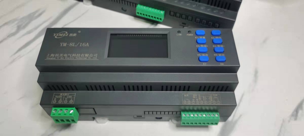
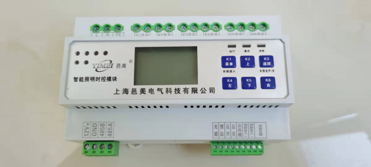
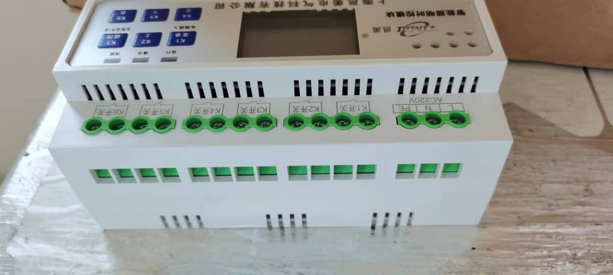
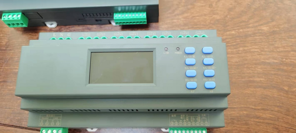
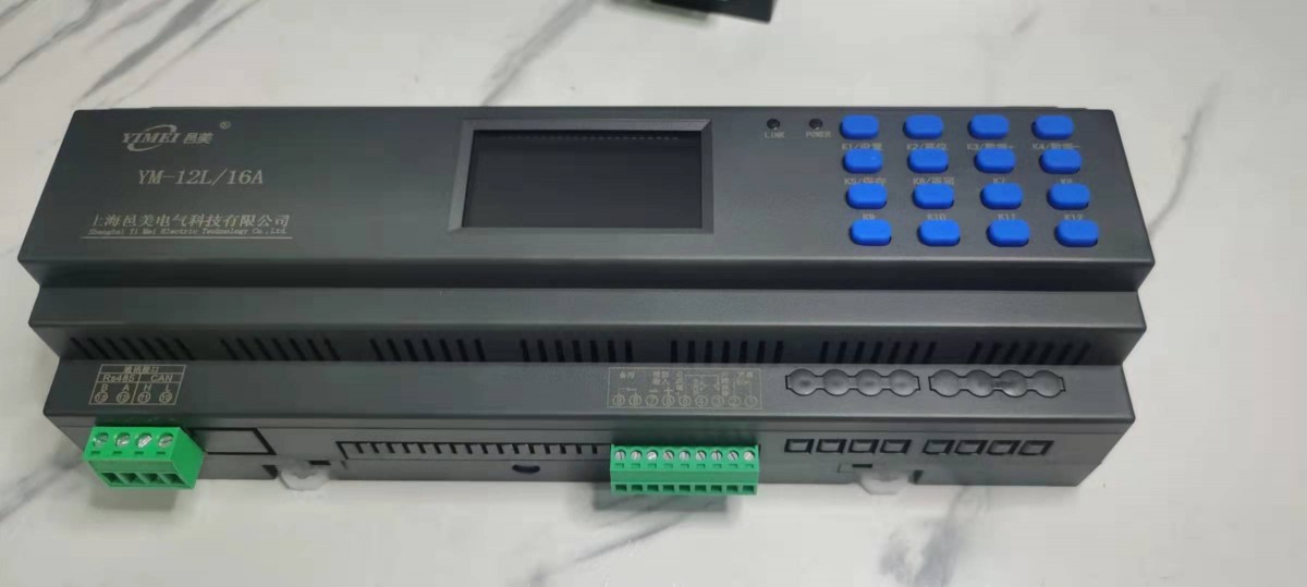
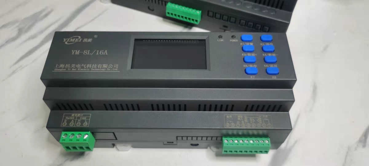
5、 Function settings 1. Interface display button K1K2K3K4K5K6K7K8K9K10 K11 K12 K13 K14 K15 K16 Function long press to enter the setting state, short press the 1 circuit on/off setting state shift button, digital display long press to display the illuminance value, short press the 2 circuit on/off setting state data increase button, short press the 3 circuit on/off setting state data decrease button, short press the 4 circuit on/off setting state save button, short press the 5 circuit on/off setting state return button, short press the 6 circuit on/off button, short press the 7 circuit on/off button, short press the 8 circuit on/off button, short press the 9 circuit on/off button, short press the 10 circuit on/off button. Circuit on/off short press 12 circuit on/off short press 13 circuit on/off short press 14 circuit on/off short press 15 circuit on/off short press 16 circuit on/off set shift data+data-
Save and return K1 K2 K3K5 K6K4 public terminal 1 1 2 3 5 4 6 7 8 9 feedback output fire input 10 11 12 13Rs485 CAN B A L H
2. Button Definition 01 02 03 04 Set Shift Data+Data-
Save and return K1 K2 K3K5 K6K4 public terminal 1 1 2 3 5 4 6 7 8 9 feedback output fire input 10 11 12 13Rs485 CAN B A L H Dark: Dawn:
Intelligent lighting time controller
ID: Illumination:
: 01 02 05 06 09 10 13 14 03 04 07 08 11 12 15 16 . Reported on Sunday, Month, Day:
Digital display LCD display
3. Function settings, address settings, display code settings, long press the settings button, display press the settings button, display press K2 to shift, K3 increases data, press K4 to decrease data, adjust the required address, press K5 to save data, display K6 to return to the upper menu, long press the setting key for address 1, display K3 to adjust to press the setting key, display K2 to shift, K3 increases data, press K4 to decrease data, adjust the required address, press K5 to save data, display K6 to return to the upper menu, set the circuit time, long press the setting key, display K3 to adjust to press the setting key, display the time before setting, press K2 to shift, K3 to increase data, press K4 to decrease data, adjust the required time, press K5 to save data, display K6 to return to the upper menu, long press the setting key, display K3 to adjust to press the setting key, display the cursor Flashing position, for this circuit turn on, represents turn off, represents turn on, represents turn off, represents turn on, represents turn off, represents turn on, represents turn off, represents turn on,
Represents turning off lights, representing 'hour' represents' minute '
When the 1st light is on, it indicates the road setting. Press the setting button, and the numeric cursor will flash. Then press the setting button again, and press K2 to shift,
K3 increases, press K4 to decrease data, adjust the timed light on time, press K6 to enter the light off setting, press K2 to shift, press K3 to increase K4 to decrease data, adjust the timed light off time. If more time periods are set for this circuit, follow the above method to loop through the settings. If you need to set the next circuit, when the cursor is flashing, press K2 to shift the next time, mark the next street light, and set the required time control in sequence according to the above method. If all circuits have the same on/off time, only the circuit data can be saved, and then the setting unit can be operated to batch copy the circuit setting data. Press K5 to save data, display control settings when pressing K6 to return to the upper menu
Function settings display code setting steps. Long press the setting key to display. Press the K3 key to adjust to the setting key. Display
When the 1st light is on, it indicates the road setting. Press K5 to save the data, and press K6 to return to the upper menu for latitude and longitude
Enable by pressing the settings button and modifying it as follows: This value is the latitude and longitude enable value. Press K2 to shift, K3 to increase data, K4 to decrease data, adjust the desired start value, press K6 to return, and then press K2 to shift to the next circuit where the light bulb lights up. You can set the corresponding circuit start value for the light bulb. By following the above method, more circuit latitude and longitude start values can be set. If all circuits have the same on/off time, only the circuit data can be saved, and then the setting unit can be operated to batch copy the circuit setting data. After saving the data, you can view the on/off light time values in latitude and longitude. Press the settings key, press the K3/K4 key, and change the flashing cursor to indicate the latitude and longitude light on time
Turn off time, this value can only be viewed and cannot be modified. If you need to set the midnight light mode, you can adjust the flashing cursor and the light on time. This time value is set to the time after the latitude and longitude start, which is the light off time value. Before setting the latitude and longitude, it is necessary to calibrate the local latitude and longitude values in the settings bar by long pressing the settings button. Press the K3 button to adjust to the settings button, press K5 to save the data, and press K6 to return to the upper menu for batch control
Press and hold the settings button to display the K3 key to adjust to latitude, longitude, year, month, and day
Calibration: Press the settings button to display and adjust the "latitude". Press the settings button to enter, press K2 to shift, press K3/K4 to add or subtract data, and press K6 to return; Press the K3 data key to display
Adjust the "longitude", press the setting key to enter, press K2 to shift, press K3/K4 to add or subtract data, press K6 to return; Press the K3 data key to display and adjust the "year", press the settings key to enter, press K2 to shift, press K3/K4 to add or subtract data, and press K6 to return; Press the K3 data key to display and adjust the "month", press the settings key to enter, press K2 to shift, press K3/K4 to add or subtract data, press the K6 return key, press the K3 data key to display and adjust the "day", press the settings key to enter, press K2 to shift, press K3/K4 to add or subtract data, press K5 to save data, and press K6 to return to the previous menu
Function settings display code setting steps. Long press the settings button to display. Press the K3 button to adjust to the settings button. The display indicates that the light will be turned on 00 minutes in advance. Press the display button to display
Represents a delay of 00 minutes when turning on the light. Press K2 to switch between advance and delay, press K3/K4 to adjust the advance or delay time, press the settings button to display
The representative turns off the lights 00 minutes in advance, and the display shows that the representative turns off the lights 00 minutes later. Press K2 to switch between early or late, and press K3/K4 to adjust the early or late time.
Press K5 to save data and display K6 to return to the upper menu for latitude and longitude compensation
Press and hold the settings button to display. Press the K3 button to adjust the display to press the settings button. When the 1st light is on, it represents the setting circuit. The front end flashes as Monday, and you can switch to Tuesday by pressing K3/K4,
For Wednesday, for Thursday, for Friday, for Saturday,
For Sunday, to start, press the settings button, then press K3/K4 to switch to not starting. Press the return button, then press K3/K4 to switch and set other weeks in sequence. When the cursor flashes, press K2 to shift and the next circuit light will turn on. Follow the above method to set other circuits and weeks in sequence. Week mode
Press K5 to save data, press K6 to return to the upper menu, press and hold the settings button, press K3 to adjust to the settings button, and display as the fire linkage fully open mode. Press K3/K4 to switch to the fire linkage fully closed mode. Press K5 to save data, display K6 to return to the upper menu, press and hold the settings button, display K3 to adjust to the settings button, display as a switch self-locking signal, press K3/K4 to switch to a switch jog signal. Press K5 to save data and display K6 to return to the higher-level menu for fire linkage
Settings
Switching signal setting
Function settings display code setting steps. Press and hold the setting button to adjust the display. Press and hold the K3 button to adjust to the setting button. The display shows a delay of 100 milliseconds for each circuit relay to turn on and off. Press K2 to shift and press K3/K4 to adjust the data. The adjustment value is 100-1000 milliseconds. Press K5 to save data, display K6 to return to the upper menu
Drive delay
Press and hold the settings button to display. Press the K3 button to adjust to the settings button, which displays a baud rate of 9600bps. Press the K3/K4 button to switch
Change (2400bps) (4800bps) (14400bps)
(19200bps) (115200bps) Press K5 to save data, display K6 to return to the upper menu
Baud rate
Press and hold the settings button to display. Press K3 to adjust to light sensing settings. Press K5 to save data. Press K6 to return to the upper menu. Press and hold the settings button to display. Press K3 to adjust to settings. Press K3/K4 to switch (off) (on). Press K5 to save data. Press K6 to return to the upper menu. Press and hold the settings button to display. Press K3 to adjust to settings. Press K5 to save data. Press K6 to return to the upper menu. Open the box and sound an alarm
Set factory reset
Press the setting button to display the set value of the turn off sensor switch. The device will automatically determine whether it is positive or negative as the switch value. For example, if the set value is 50, the device will determine that the on/off value is 44 and the off value is 56. The set value can be adjusted according to K3/K4. Press the setting button to light up the 1st circuit indicator, indicating that the road light sensing is turned off. Press K3/K4 to switch, indicating that it is turned on. Press the setting button to switch to the next circuit setting
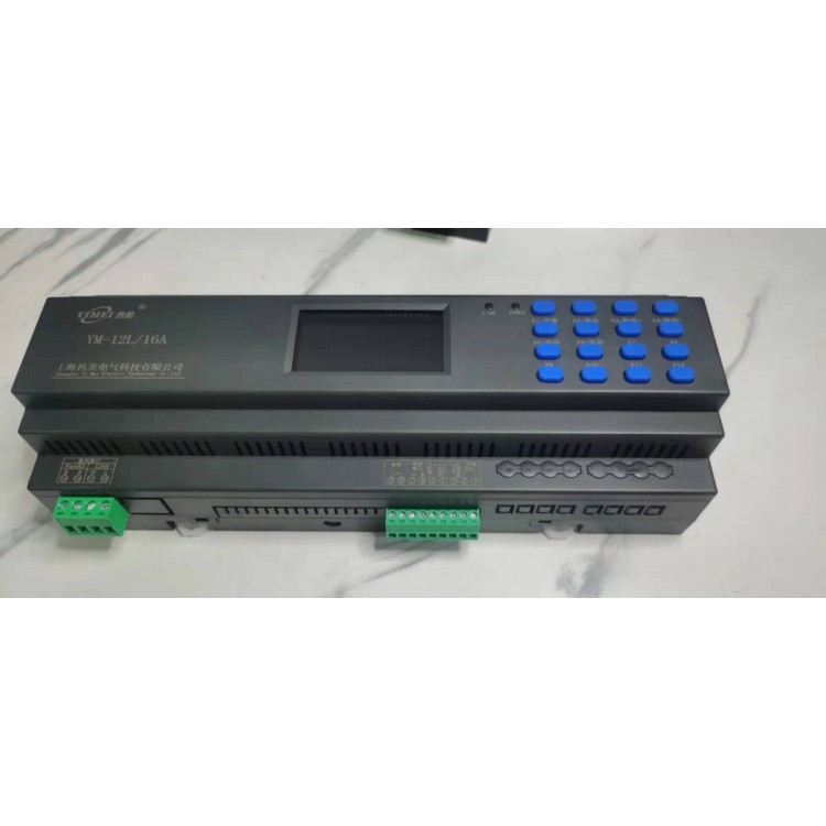
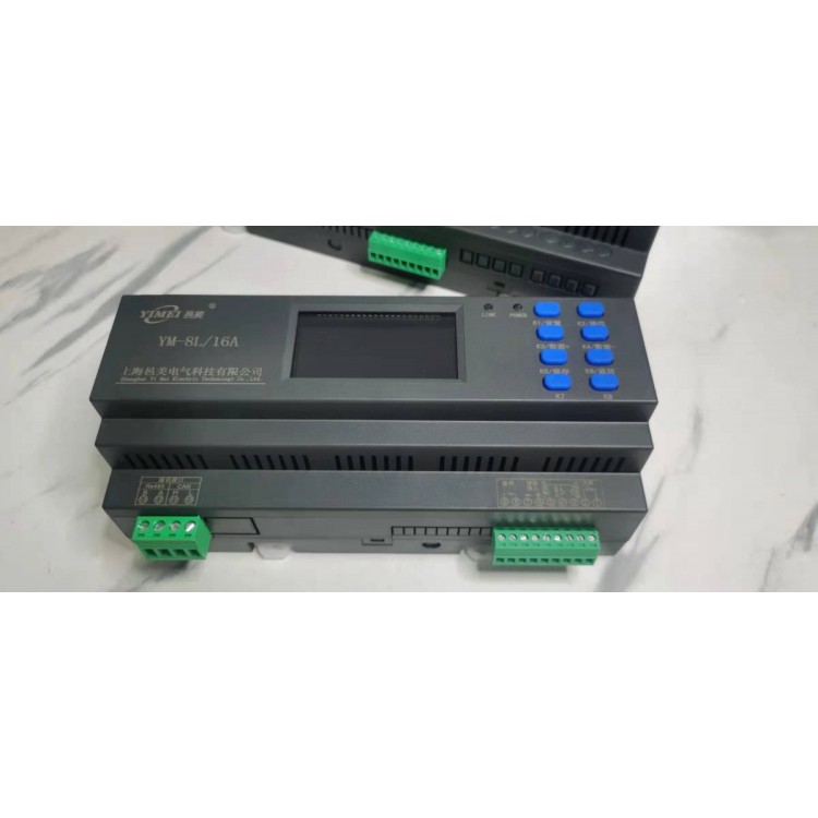
6、 Installation size seven, precautions
Proper use of equipment power supply.
The product comes with a one-year warranty,
1. Power usage
2. Repair and replacement
3. Without the consent of our company, no one is allowed to open the centralized controller or perform maintenance on the product storage
According to the national standard GB 13955-2005, the working life of this device is six years. At that time, it should be repaired
Replace it. The storage location should be clean and dry, with an ambient temperature of -40~85 ℃ and a relative humidity not exceeding
85, and there are no harmful substances in the air that can cause corrosion.
The product should not be subjected to severe impact during transportation and unpacking, and in accordance with GB/T1546-1995 "Instrumentation
According to the Technical Conditions for Packaging and Transportation, transportation is regulated.
4. Product transportation settings shift data+data-
Save and return K1 K2 K3K5 K6K4 common terminal 1 1 2 3 5 4 6 7 8 9 feedback output fire input 10 11 12 13Rs485 CAN B A L H A B D C EH G F 4 circuit specifications A (length) 108mm 180mm 252mm 252mm 6 circuits 8 circuits 12 circuits 16 circuits B (width) 95mm 95mm 95mm 95mm 95mm 95mm C (height) 68 mm 68mm 68mm 68mm 68mm D 65mm 65mm 65mm 65mm 65mm E 45mm 45mm 45mm 45mm 45mm H 35mm 35mm 35mm 35mm 35mm F 40mm 40mm 40mm 40mm 40mm G 16mm 16mm 16mm 16mm 16mm
8、 Product warranty, product warranty card related information (to be filled in by the user unit), user unit contact phone number, mailing address, purchase store, product name, product model, purchase date, usage item, fault description, return to factory for repair (to be filled in by the repair personnel), repair date, handling method 1, fault content 1, repair unit fault content 2, repair personnel signature handling method 2, fault content 3, handling method 3, contact phone number