


During transportation and processing, it is often necessary to flip parts. Traditional methods generally use overhead cranes to achieve flipping. This lifting flipping method is more suitable for rough large components, but for components with high precision requirements and special shapes, it is often necessary to design flipping machines that meet specific requirements. In stamping applications, the completion of workpiece stamping often requires flipping the upper and lower surfaces and sending them to the next stamping process for stamping. Traditional stamping production relies on manual flipping, but with the continuous improvement of stamping automation, robot assisted stamping automatic production lines are gradually replacing traditional flipping methods. Among them, two six degree of freedom robots are used, which can directly exchange flips between the two For the use of a five degree of freedom non-standard robot, it is necessary to use a temporary feeding platform to achieve workpiece flipping and transfer For the use of a four degree of freedom non-standard robot, it can be completed by combining two non-standard robots and one flipping machine. This article focuses on the design of a flipping machine system using a four degree of freedom non-standard robot.
1 Mechanical structure design
1.1 Flip requirements
Firstly, the robot places the workpiece on the feeding platform of the flipping machine. The flipping machine senses the workpiece and then flips it, thus achieving the exchange of the upper and lower surfaces of the placed workpiece. To achieve this requirement, it is generally required to clamp the workpiece after it is placed, and the rotating mechanism should flip it over 180Release the clamping mechanism.
1.2 structural design
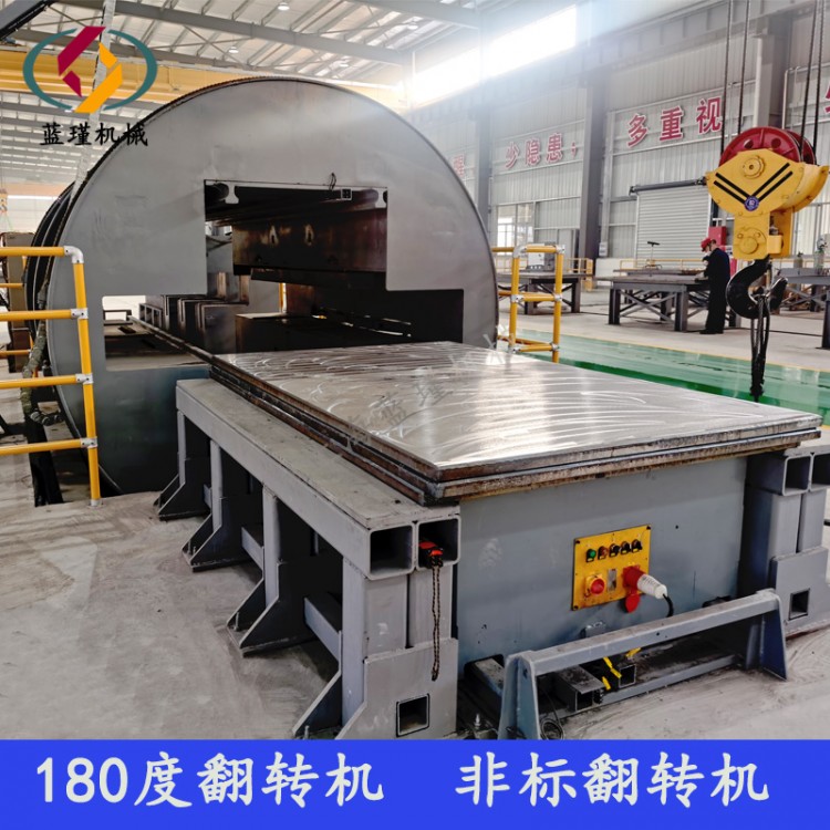
The mechanical structure of the left and right flipping machine is shown in the diagram 1 As shown. The entire mechanism is mainly composed of three parts: workpiece clamping mechanism, flipping mechanism, and support frame. Among them, the workpiece clamping mechanism mainly consists of a telescopic cylinder, an aluminum profile material support bracket, and multiple positioning blocks; The flipping mechanism is composed of a stepper motor with a reducer, a diaphragm coupling, bearings, and a rotating support plate, which are fixed on the rotating support plate. The designed transmission ratio of the reducer is15∶1 The support frame is mainly composed of a rectangular bottom box and two columns with crossbars. The control box is placed inside the bottom box, and the three color alarm indicator lights are fixed on the crossbars.
2 Control Design
The entire action sequence of the flipping machine is as follows :
(1)Place the material on the lower cover plate, position it with the positioning block, and push the upper cover plate of the flipping table downwards by the cylinder to close the upper and lower cover plates, achieving clamping of the workpiece;
(2)Flip the table clockwise180After flipping in place, the cover plate on the flipping table is moved up, and the upper and lower cover plates are opened to achieve the exchange of the upper and lower surfaces of the material;
(3)Take away the materials and complete a flipping action;
(4)Re insert the material, activate the cylinder, and close the upper and lower cover plates;
(5)Flip the table counterclockwise180°;
(6)The cylinder moves and the upper and lower cover plates open.