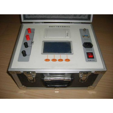
Description of Grounding Resistance Tester
7. Place the "preset/test" switch in the "preset" state, adjust the "alarm resistance adjustment" potentiometer, and preset the alarm resistance value to 500m Ω. (The alarm resistance value can only be preset when there is a current output). After adjusting the preset alarm resistor, press the "Reset" button to cut off the output current, and at the same time turn the "Current Adjustment" knob to a small position to separate the short circuited test clip. 9. Pre test inspection: Short circuit the test clamp, adjust the current knob to a current value of 5A, disconnect the test clamp, and if the instrument issues an alarm, the inspection is qualified. Otherwise, it is unqualified.

Grounding resistance tester type
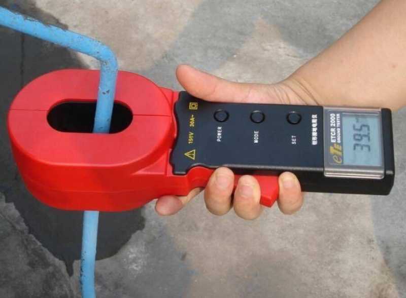
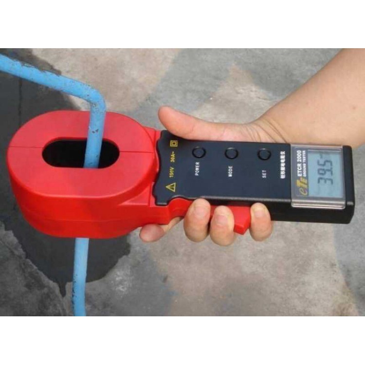
At present, there are various grounding resistance testers on the market, and their measurement methods mainly include two types: clamp method and ground pile method. When measuring grounding resistance using the clamp method, there is no need to use auxiliary grounding rods or interrupt the grounding of the tested equipment. As long as the grounding wire or rod is clamped, the grounding resistance of the grounding body can be measured. The piling method can be divided into two line method, three line method, and four line method. The two-line method is the initial measurement method, which involves connecting one wire to the tested grounding body and the other wire to the auxiliary electrode. The measurement results of this method have significant errors. The three line method is an improved version of the two line method, which uses two auxiliary poles. Through formula calculation, when the middle auxiliary pole is 0.62 times the total length, it can basically eliminate errors caused by ground pile resistance. The four line method is an improved method based on the three line method. It can eliminate errors caused by auxiliary electrode grounding resistance, test leads, and contact resistance.
Customized grounding resistance tester
Visual inspection of the calibration items for the grounding resistance tester. Whether the appearance of the instrument is damaged, whether the switch buttons are flexible, and whether the digital display indication is incomplete. Are the random attachments complete. Alarm threshold setting error. The standard resistor method is adopted, and the wiring method is the same as the method for verifying the indication error. The verification is carried out at the resistance points of 1 Ω, 4 Ω, 10 Ω, 30 Ω, and 100 Ω. Indicate accuracy check. The two ends of the grounding resistance meter are respectively connected to terminals 14 and 16 of the running instrument; Alarm the grounding resistance tester to the preset value of 1V; the measured value of the grounding resistance tester indicates within 0.1 ohm ± 5% and alarms simultaneously (if indicated, it should indicate 1.0V ± 5%). The tested technical parameters and functions are all normal; The measured value of the grounding resistance tester is within 0.1 ohms ± 5% but there is no alarm. Then, turn the testing terminal from position 14 to position 17. At this point, if the tested grounding resistance tester alarms, it indicates that the technical parameters and functions of the tested instrument are also normal; If the inspection result is outside of the two situations mentioned in the book, it indicates that the inspected instrument is not working properly.