


- AllProduct Category
-
Waste Gas Treatment Equipment
Wastewater Treatment Equipment
River Purification Equipment
Laboratory Pure Water Systems
Reclaimed Water Equipment
EDI Ultra-Pure Water Equipment
Deionized/Demineralized Water Equipment
Reverse Osmosis Pure Water System
Water Softener, Ion Exchange System
GMP Pharmaceutical Purification Water Equipment


详情描述
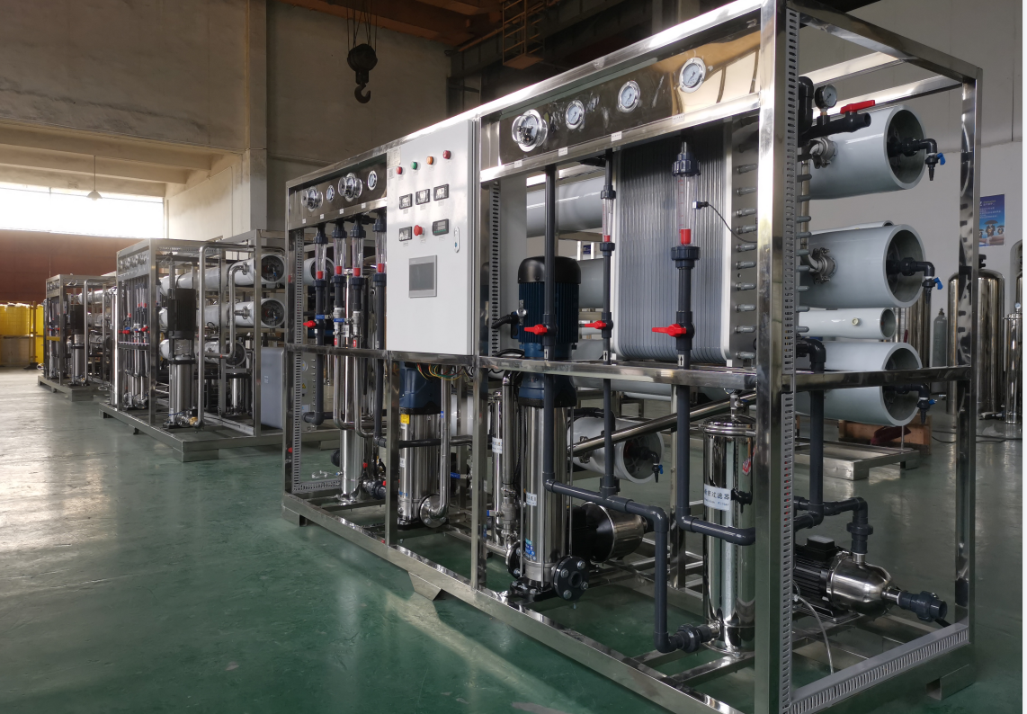
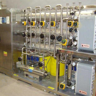
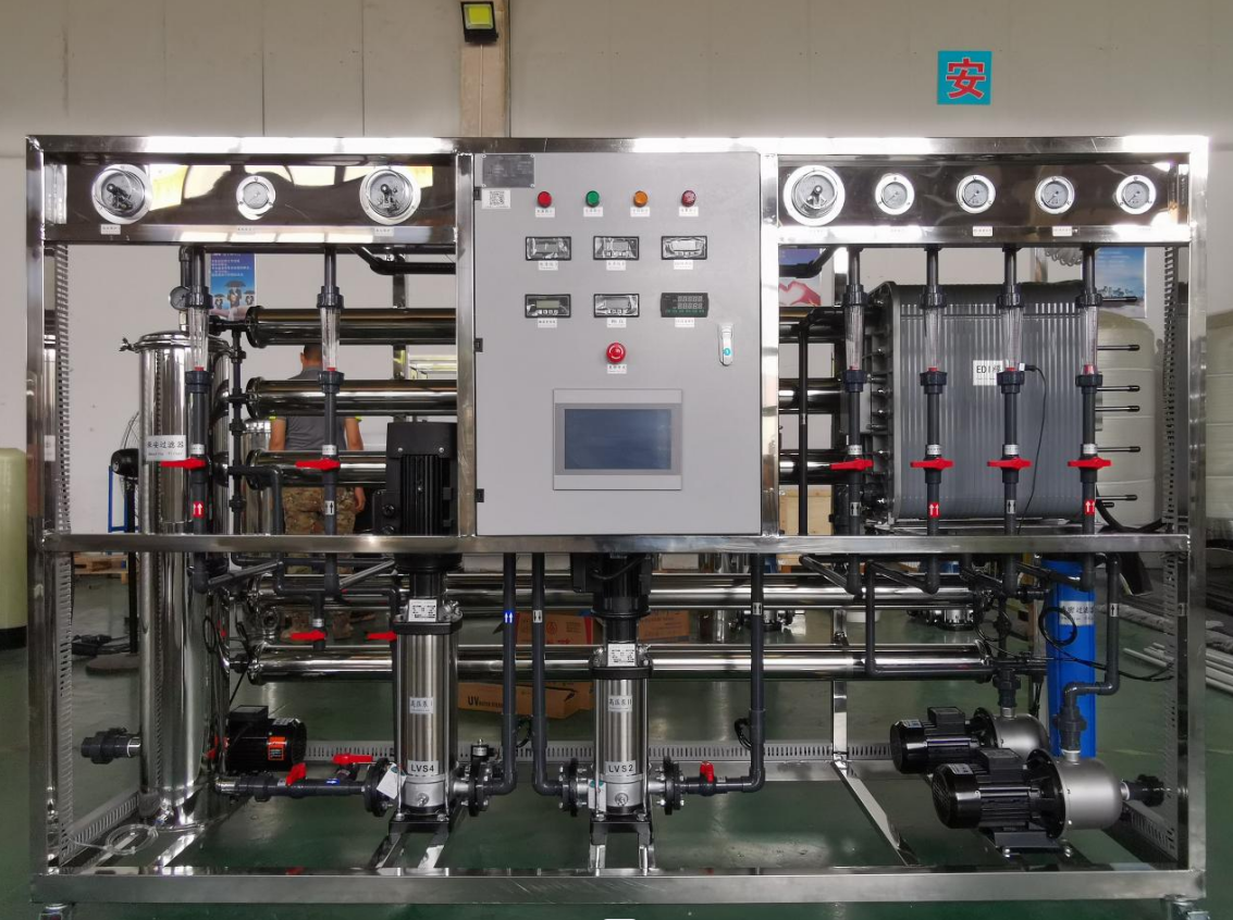
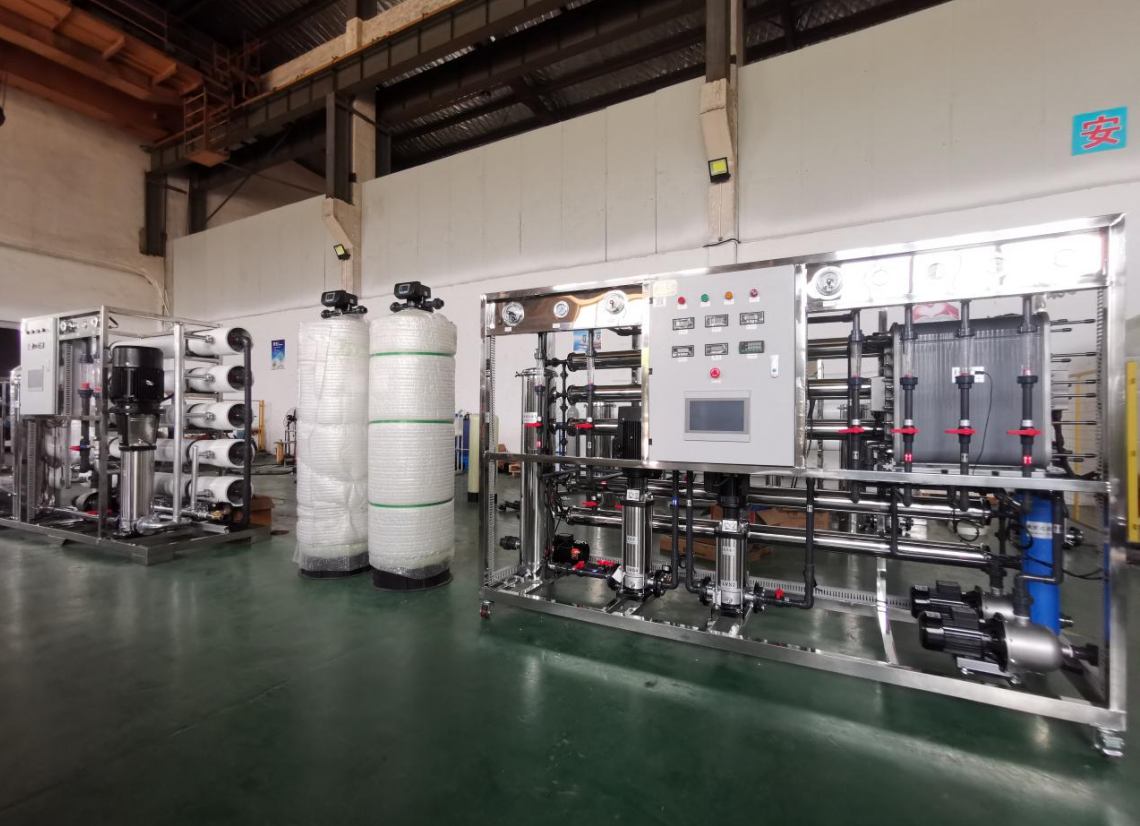
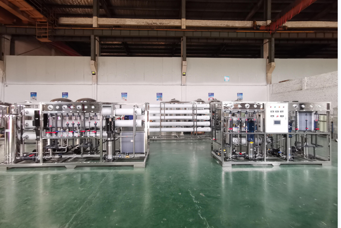
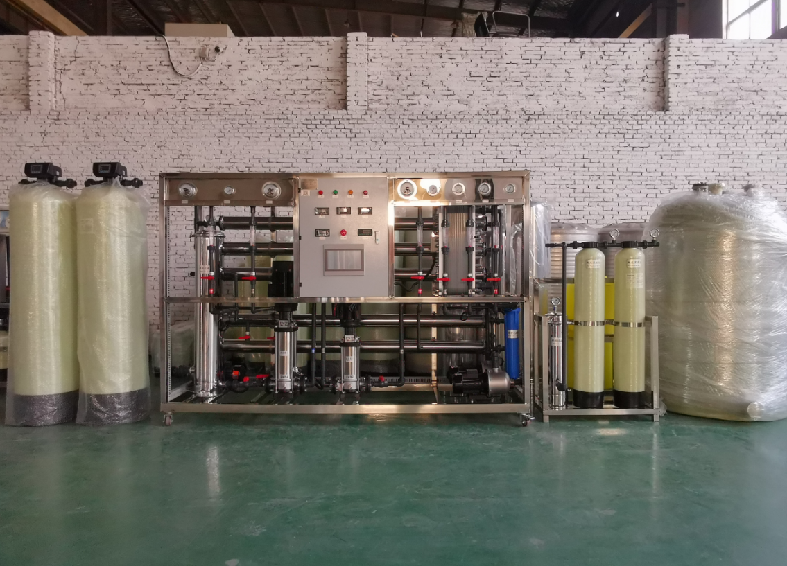
Main Applications of Ultra-Pure Water Equipment:
1. Semiconductor Industry: Used for wafer cutting (6-12 inches), cleaning, regeneration, water for semiconductor packaging and testing, cleaning of semiconductor equipment, and cleaning of electronic-grade dust-free fabrics and protective suits.
2. Solar Photovoltaic Industry: Monocrystalline silicon, polycrystalline silicon wafer cleaning, solar cells, quartz crucibles, polycrystalline silicon boats, photovoltaic glass, high-purity silicon powder.
3. LCD, LED, OLED production cleaning water, optical camera cleaning, optical material cleaning, conductive glass cleaning.
4. Ultra-pure water for cleaning semiconductor integrated circuit boards and printed circuit boards.
5. Lithium-ion battery materials (lithium iron phosphate, ternary materials, lithium-ion battery separators), lead-acid batteries, and zinc-manganese battery production water.
6. Pure water for electronic-grade ultra-pure chemicals, nanometer-grade electronic ceramic materials, sharp magnetic materials, and aviation new material production.
7. Non-ferrous metals, precious metal smelting water, aviation new material production water, capacitor material etching process water, vacuum coating, high-purity inks, etc.
Design Standards for Ultra-Pure Water Equipment:
Electronics Industry Pure Water System Design Specification GB50685-2011
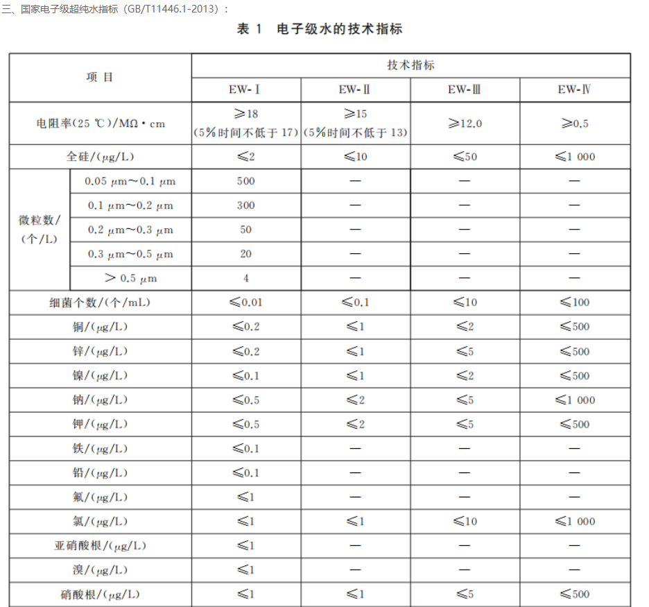
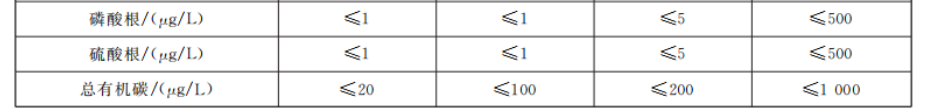
National Standard of China for Electronic Grade Ultra-Pure Water - GB/T11446.1-2013
General Rules for Electronic Grade Water Test Methods GB/T 11446.3-2013
Testing Method for Resistivity of Electronic Grade Water - GB/T11446.4-2013
Atomic Absorption Spectrophotometric Method for Trace Metals in Electronic Grade Water - GB/T114465-2013
Method for Ion Chromatographic Analysis of Trace Anions in Electronic Grade Water - GB/T11446.7-2013
Test Method for Total Organic Carbon in Electronic Grade Water - GB/T 11446.8-2013
Method for testing instrumental analysis of electronic-grade water particles - GB/T 11446.9-2013
Method for Membrane Filtration and Culture Test of Total Bacterial Count in Electronic Grade Water - GB/T 11446.10-2013
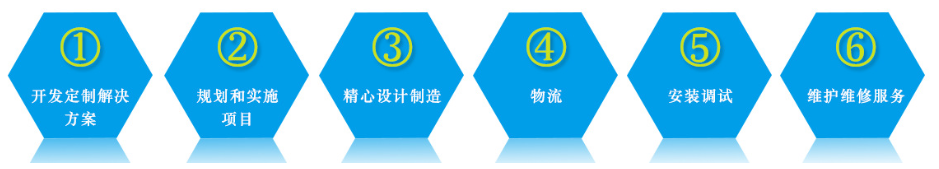
※MidPure Eco-Friendly Brand 『Design Advantages』:
1. Personalized one-on-one services, complimentary on-site survey, considering placement area and entry space, and free original water quality testing.
2. Understand the customer's full-day water demand, peak water usage, quality requirements, and learn about the customer's production process and industry characteristics.
3. Professional team collaboration with design, coupled with on-site inspections by dedicated service personnel, and one-stop water treatment solution services.
4. Intelligent design with precise control and high level of automation. Units can achieve automatic forward/backward washing and operation, with interlock protection and alarm indication. Data is available for 4-20mA open-loop transmission, allowing remote transmission to the DCS central control system, truly realizing unattended operation.
5. Segmentally inspect according to process requirements, capable of measuring conductivity, resistivity, pH, ORP, temperature, flow rate, velocity, and pressure, ensuring that water quality meets standards at every process stage and does not contaminate finished product water downstream, emphasizing process control.
6. Design products tailored to the customers based on a balanced consideration of comprehensive investment and operational costs.
※Pure Environmental Protection Brand 『Production Advantages』:
1. Core components are all imported, and we have established long-term cooperative relationships with numerous international brands such as Dow, Hydronix, GE, Siemens, Rhone-Poulenc, Grundfos, Rosemount, Nippon Paint, and Schneider, ensuring reliable product quality.
2. Vendors conduct product assessments, eliminating suppliers with poor quality and service, and selecting the top-performing ones to enter the qualified supplier system.
3. Strictly adhere to the quality management system; quality is paramount. Conduct incoming material appearance and performance inspections, in-process inspections, and final product quality checks.
4. Production staff produce according to assigned numbers, work in shifts in groups, and are responsible for their respective tasks. Performance assessment and traceability are robustly established.
5. Pre-shipment trial operation inspection, electrical point operation test, to ensure delivery of qualified products to the customer.
※ Pure Environmental Protection Brand 『After-Sales Advantages』:
1. Professional installation and after-sales team offering one-on-one service, enhancing the timeliness of post-installation after-sales support and improving customer satisfaction.
2. Establish a post-installation after-sales service system, conduct performance evaluations, set up a customer service department, a complaint hotline, and promptly address customer needs.
3. Full guidance and training throughout the installation and debugging process, including theoretical training, hands-on machine operation training, and general troubleshooting training.
4. Establish customer electronic profiles, conduct monthly phone follow-ups, and promptly provide methods and suggestions for reducing equipment operation costs.
5. Multiple channels for after-sales feedback, nationwide after-sales maintenance services, quick response, fast handling, 24/7 service.
6. We solemnly promise: two years of free warranty for the entire unit, lifetime free technical support.
Section 1: Recommended Ultra-Pure Water Production Process
1. Grade 1 RO + EDI + Mixed: Product water resistivity ≥ 18 MΩ·cm (25℃), other indicators meet the specifications for electronic-grade ultra-pure water
Source Water → Source Water Tank → Booster Pump → Sand Filter → Carbon Filter → Softener/Scale Inhibitor → Security Filter → High-Pressure Pump → First Stage Reverse Osmosis → First Stage Storage Tank → Booster Pump → Fine Filter → EDI Desalination Unit → Ultra-Pure Water Tank (recommended with nitrogen protection) → Transfer Pump → Polishing Mixed Bed → UV/TOC → Fine Filter → Water Usage Point → Return Water (recommended with pipeline circulation, no dead water)
Note: This process requires good quality of raw water; otherwise, it may cause irreparable damage to the EDI desalination system.
2. Grade 2 RO+EDI+Blending: Product water resistivity ≥ 18 MΩ·cm (25°C), all other specifications meet the standards for electronic grade ultra-pure water
Source Water → Source Water Tank → Boost Pump → Sand Filter → Carbon Filter → Softener/Scale Inhibitor → Security Filter → High-Pressure Pump → Primary Reverse Osmosis → Primary Water Tank → PH Adjustment → High-Pressure Pump → Secondary Reverse Osmosis → Secondary Water Tank → Boost Pump → Fine Filter → EDI Desalination Unit → Ultra-Pure Water Tank (recommended with nitrogen protection) → Transfer Pump → Polishing Mixed Bed → UV/TOC → Fine Filter → Water Usage Point → Return Water (recommended with pipeline circulation, no dead water)
Note: If there is a high requirement for particulate matter and TOC, it is recommended to set up a dedicated ultrafiltration (UF) membrane (Asahi Kasei from Japan) for removing particulate matter and TOC in the later stage.
3. Disk filter + UF + Secondary RO + EDI + mixed: Product water resistivity ≥ 18 MΩ·cm (25°C), other specifications meet the standard for electronic grade ultra-pure water.
Raw Water → Raw Water Tank → Booster Pump → Plate Filter → Bag Filter → Ultrafiltration UF → Ultrafiltration Tank → Intermediate Pump → Security Filter → High-Pressure Pump → Primary Reverse Osmosis → Primary Water Tank → PH Adjustment → High-Pressure Pump → Secondary Reverse Osmosis → Secondary Water Tank → Booster Pump → Fine Filter → EDI Desalination Unit → Ultra-Pure Water Tank (recommended nitrogen protection) → Feed Pump → Polishing Mixed Bed → UV/TOC → Fine Filter → Water Usage Points → Return Water (recommended pipeline circulation, no dead water)
Note:
1. If there is a high requirement for particulate matter and TOC, it is recommended to set a dedicated ultrafiltration (UF) membrane (Asahi Kasei, Japan) for particle removal and TOC指标 in the downstream section.
2. The above process is a full-film process
3. Grade 1 RO + Grade 3 mixed: Product water resistivity ≥ 18 MΩ·cm (25°C), the rest of the indicators meet the specifications for electronic grade ultra-pure water.
Source Water → Activated Carbon Filter Core → 10um Filter Core → 5um Filter Core → High-Pressure Pump → Reverse Osmosis (RO) System → Primary Polishing Mixed Bed → Secondary Polishing Mixed Bed → Tertiary Polishing Mixed Bed → Fine Filter → Ultra-Pure Water Tank (recommended with nitrogen protection) → Feed Pump → UV/TOC → Fine Filter → Water Point → Return Water (recommended with pipeline circulation, no dead water)
Note: Suitable for small ultra-pure water units; Flow range: 50L/H - 200L/H
For more product details, please call our 24-hour hotline at 18550863818 or the national hotline at 0512-69390898.
We will provide you with detailed plans, drawings, and competitive quotes for your reference and selection!
Call for consultation, enjoy 10% off! Welcome to call!
Section II: Introduction to the Core Technology of EDI Ultra-Pure Water
Ultrafiltration (UF) System
The primary function of the ultrafiltration system is to separate suspended large molecules, colloids, slime, microorganisms, organic matter, and other impurities that can cause fouling of reverse osmosis membranes. This includes the backwashing and sterilization dosing system, ultrafiltration unit, and backwashing pump, etc. Ultrafiltration (abbreviated as UF) is a physical screening process that separates liquids using the pressure-driven force and the different pore sizes of ultrafiltration membranes. Ultrafiltration membranes are typically asymmetric in structure, consisting of a very thin (usually less than 1μm) skin layer with a specific pore size and a thicker (usually 125μm) porous layer with a spongy or finger-like structure. The former serves the separation function, while the latter provides support. The typical pore size of ultrafiltration membranes is between 0.01 and 0.1 micrometers, offering a high removal rate for bacteria, most pathogens, colloids, sludge, etc. The smaller the nominal pore size of the membrane, the higher the removal rate. Ultrafiltration membranes commonly use high molecular polymer materials. For ultrafiltration, the widely used descriptive analysis of the separation mechanism is the "screening" theory. The ideal ultrafiltration membrane separation process is the screening out of solvents and small solute particles from the high-pressure side of the feed liquid through the low-pressure side of the membrane under pressure, as larger molecules and microparticles are blocked by the membrane, causing the feed liquid to gradually concentrate; larger molecules, colloids, proteins, and microparticles in the solution are retained by the ultrafiltration membrane and recovered as concentrate. However, in practice, the separation process of ultrafiltration membranes involves different retention effects due to the pore size of the membrane and the chemical properties of the membrane surface, so the ultrafiltration phenomenon cannot be simply analyzed. Ultrafiltration membranes have important characteristics in their pore structure, as well as chemical properties on the membrane surface. Performance indicators of ultrafiltration membranes include permeate flux and retention rate. The pressure resistance, cleaning resistance, and temperature resistance of ultrafiltration membranes are very important for industrial applications.
The membrane components are available in four types: plate, scroll, tubular, and hollow fiber, categorized by the position of the separation layer into: internal pressure, external pressure, and internal-external pressure. Hollow fiber membranes are one of the primary types of ultrafiltration membranes, having a capillary-like structure, spun from fibers. Their inner or outer surface is a dense layer, also known as the active layer, with a porous support inside. The dense layer is densely packed with micropores, and the separation is achieved based on whether the solution components can pass through these micropores. The feed solution flows under pressure through the hollow fiber membrane's inner or outer pores, while the filtered liquid exits from the opposite side.
2. Reverse Osmosis (RO) System
Reverse osmosis (RO) membranes, also known as anti-permeation membranes, are a high-tech membrane separation technology invented by Loeb and Sourirtajan of the University of California, Los Angeles in 1960. Their pore size is as small as nanometers (1 nanometer = 10^-9 meters). Under certain pressure, H2O molecules can pass through the RO membrane, while inorganic salts, heavy metal ions, organic matter, colloids, bacteria, viruses, and other impurities in the source water cannot pass through the RO membrane, thus strictly separating the pure water that can pass through from the concentrated water that cannot.
Principle: Osmosis is a physical phenomenon where water from a solution with lower salt concentration passes through a semi-permeable membrane into a solution with higher salt concentration until both are equal in concentration. However, this process takes a long time and is known as natural osmosis. If a pressure is applied to the side with higher salt concentration, it can stop the osmosis, and this pressure is called osmotic pressure. Increasing the pressure can cause the water to permeate in the opposite direction, leaving the salt behind. Therefore, the principle of reverse osmosis desalination is to apply a pressure greater than the natural osmotic pressure to saltwater (such as raw water), causing the water molecules to be pushed to the other side of the membrane, resulting in clean water. This process removes salt from the water, thus achieving desalination.
Reverse osmosis membranes use aromatic polyamide spiral wound composite membranes. The reverse osmosis system consists of composite membrane elements, high-pressure pumps, glass fiber reinforced pressure vessels, chemical cleaning equipment, brackets, and instrument control cabinets. Equipped with a local control panel, which is fitted with various local instruments and control buttons. The reverse osmosis desalination unit is controlled by a PLC and operates automatically. It is equipped with flowmeters, pressure gauges, conductivity meters, and more.
3. pH Regulation System
Due to the RO membrane's inability to remove carbon dioxide, it remains in the reverse osmosis permeate, forming carbonic acid and increasing conductivity. By adding alkali to the primary RO permeate and adjusting the pH to around 8.2, carbon dioxide can be converted into bicarbonate ions, which are then removed by the secondary RO membrane, ensuring the secondary RO permeate meets specifications.
The pH adjustment system is fully automated, equipped with a metering pump to automatically add diluted NaOH solution to the pipeline. It offers precise measurement, a lightweight overall design, and accurate speed control, unaffected by heat sources or electromagnetic interference. With real-time monitoring by the pH online monitoring instrument, it automatically adds chemicals to ensure the stable water quality of the secondary RO product.
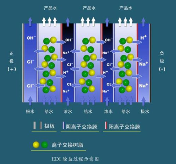
4. EDI Deionization System
EDI equipment, Continuous Electrical Deionization (EDI), utilizes mixed ion exchange resins to adsorb the positive and negative ions in the feedwater. Simultaneously, these adsorbed ions are removed by passing through the respective anion and cation exchange membranes under the influence of direct current voltage. The ion exchange resins are electrochemically continuously regenerated, eliminating the need for acid and alkali regeneration. This new technology can replace traditional ion exchange (DI) units to produce ultra-pure water with a resistivity of ≥15MΩ.CM. The working principle of the ion exchange membrane is similar to that of the ion exchange resin, selectively allowing ions to pass through. An anion exchange membrane permits only anions to pass while blocking cations, and vice versa for a cation exchange membrane. Filling the space between a pair of anion and cation exchange membranes with mixed ion exchange resins forms an EDI unit. The space between the anion and cation exchange membranes filled with mixed ion exchange resins is called the freshwater chamber. Arranging a certain number of EDI units in a row, alternating anion and cation exchange membranes, and adding special ion exchange resins between the membranes creates a brine chamber. Under the applied direct current voltage, in the freshwater chamber, the positive and negative ions in the ion exchange resins migrate towards the positive and negative poles, respectively, and pass through the anion and cation exchange membranes into the brine chamber. Simultaneously, the ions in the feedwater are adsorbed by the ion exchange resins, occupying the voids left by the ion electro-migration. In fact, ion migration and adsorption occur simultaneously and continuously. Through this process, the ions in the feedwater pass through the ion exchange membranes into the brine chamber and are removed to become desalinated water. Negatively charged anions (e.g., OH-, Cl-) are attracted to the positive pole (+) and pass through the anion exchange membrane into the adjacent brine chamber. Subsequently, these ions encounter the adjacent cation exchange membrane during their migration towards the positive pole, which does not allow anions to pass, and these ions are thus blocked in the brine. Positively charged cations (e.g., Na+, H+) in the freshwater are similarly blocked in the brine chamber. In the brine chamber, the ions passing through the anion and cation membranes maintain electrical neutrality. The electrical current and ion migration in the EDI components are proportional. The electrical current consists of two parts: one from the migration of the removed ions, and the other from the migration of H+ and OH- ions produced by the electrical ionization of water itself. A high voltage gradient exists in the EDI components, causing water to electrolyze and produce a large amount of H+ and OH-. These locally produced H+ and OH- continuously regenerate the ion exchange resins. The ion exchange resins in the EDI components can be divided into two parts: the working resin and the polishing resin, with the boundary between them being the working front. The working resin is responsible for removing most of the ions, while the polishing resin is responsible for removing difficult-to-remove ions such as weak electrolytes.
Characteristics of EDI
1. No need for acid/base regeneration, no acid/base storage or dilution transportation facilities, safe and reliable to use, and avoids worker contact with acid/base.
2. Saves regenerative water and regenerative wastewater treatment facilities
3. Reduced operating and maintenance costs
4. Compact footprint, easy installation, high water yield (up to 90-95%)
5. Continuous operation, stable product water quality, no downtime due to regeneration
5. Polished Mixed Bed System
Polished mixed beds are generally used at the end of ultra-pure water treatment systems, based on the principle of resin ion exchange. The container is filled with non-regeneration polishing mixed bed resins of nuclear grade, with ion forms being H and OH. As a terminal desalination unit, they can elevate the resistivity of the pretreatment water to the user's required level and also have certain control over TOC and SiO2.
Polished mixed bed ion exchange requires specific feedwater, which must be the product water from an anion, cation, or mixed bed ion exchange system, or from an EDI continuous electro-deionization system. Only under feedwater conditions that meet these requirements can the polished mixed bed ion exchange operate stably and long-term.
6. UV Sterilizer/TOC Remover
The UV Sterilizer/TOC Remover is a physical sterilization method. After bacteria are exposed to ultraviolet light, the energy of the ultraviolet spectrum is absorbed by the bacterial nucleic acids, altering their vitality and hindering the synthesis of proteins and enzymes within the bacteria, thereby causing mutations or death in the microorganisms. According to tests, UV light with a wavelength of 200-250nm has sterilization capabilities, with the best sterilization effect at a wavelength of 253.7nm. UV light at 185nm exhibits excellent TOC removal effectiveness. The equipment consumable is the lamp tube, which needs to be replaced regularly with a lifespan of ≥9,000 hours.
Section 3: National Standard for Electronic Grade Ultra-Pure Water (GB/T11446.1-2013)
Four: Classic Customer Case Studies:
Section 5: National Warranty and Service Network
1. Professional installation and after-sales team offering one-on-one service, enhancing the timeliness of post-installation after-sales support and boosting customer satisfaction.
2. Establish a post-installation after-sales service mechanism, conduct performance evaluations, set up a customer service department, a complaint channel, and promptly address customer concerns.
3. Full guidance and training throughout the installation and debugging process, including theoretical training, hands-on machine operation training, and general troubleshooting training.
4. Establish customer electronic profiles, conduct monthly phone follow-ups, and promptly provide methods and suggestions for reducing equipment operation costs.
5. Multi-channel after-sales feedback, nationwide after-sales maintenance services, quick response, fast handling, 24/7 service.
6. We solemnly promise: Two-year free warranty for the entire unit, lifetime free technical support.
For more product details, please call our 24-hour hotline at 18550863818 or the national hotline at 0512-69390898.
We will provide you with detailed plans, drawings, and competitive quotes for your reference and selection!
※ Phone consultation, enjoy 10% off! Welcome to call!


