
 Flexible Perforated Pipe
 Continuous filament woven geotextile
 Long-fiber Geotextile
 3D Composite Drainage Mesh
 Rigid Perforated Pipe
 Plastic Drainage Channels
 HDPE Geomembrane
 Composite Geomembrane
Product Details
Geotextiles, geogrids, geomembranes, flexible drainage pipes, rigid drainage ...


产品Price Negotiable
最小起订Quantity: 供货总Quantity:


Origin |
|
Are Custom Orders Available? |
Sure |
Available Regions |
National |
Free Shipping |
No |
Brand |
Kang Shun |
Specs |
Customer-Specified |
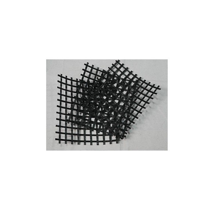
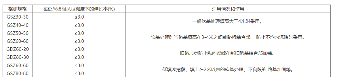
Steel-plastic reinforced geogrid is made by novel technology from steel-plastic reinforcing strips. Due to the product's surface being pressed into a regular coarse pattern, it withstands tremendous tensile stress and friction with the backfill when laid in the replacement soil layer, effectively limiting the shear, lateral extrusion, and bulging of the foundation soil. The high rigidity of the reinforced soil cushion layer facilitates the spread and even transmission of the upper foundation loads, distributing them uniformly to the underlying soft soil layer, thereby significantly improving the bearing capacity of the foundation. Thanks to the role of the reinforced soil cushion layer, the overall rigidity of the foundation soil within the compression layer is increased, which is beneficial for adjusting the deformation of the foundation. The reinforced soil composite cushion formed by using the steel-plastic reinforced geogrid is a flexible structure, capable of absorbing seismic energy effectively, hence exhibiting excellent seismic performance. Primary Application Suitable for civil engineering projects such as highways, railways, embankments, bridge abutments, construction access roads, docks, revetments, flood embankments, dams, beach reclamation, cargo yards, waste disposal sites, airports, sports fields, eco-friendly buildings, soft soil foundation reinforcement, retaining walls, slope protection, and road wear resistance. Product Features High strength, low creep, adaptable to various soil environments, perfectly meets the requirements for tall retaining walls in high-grade highways. Effectively enhances the interlocking and gripping action of reinforced load-bearing surfaces, significantly increases the bearing capacity of the foundation, effectively restricts lateral displacement of the soil mass, and strengthens the stability of the foundation. Compared to traditional gratings, our product boasts enhanced strength, load-bearing capacity, corrosion resistance, aging resistance, high friction coefficient, uniformly distributed holes, easy installation, and a longer service life. More suitable for deep-sea operations and embankment reinforcement, it fundamentally solves the technical problems of low strength, poor corrosion resistance, and short service life caused by stone baskets made of other materials due to long-term erosion by seawater. Technical Specifications Application Range Suitable for reinforced soil retaining walls, bridge abutments, slopes, and subgrade reinforcement, it improves the bearing capacity of soft foundations and resists the formation of soil破裂 surfaces. The steel-plastic composite geogrid is widely used in soft foundation treatment and the control of uneven settlement in subgrade, particularly for the treatment of uneven settlement between new and old subgrades. The steel-plastic geogrid is more effective than the plastic geogrid in dealing with uneven settlement, making it the preferred material for subgrade settlement control. When using steel-plastic composite geogrid for reinforcement in soft soil foundations, its mesh structure aids in drainage; under the load of embankment fill, water from the soft soil seeps out, promoting consolidation and increasing the bearing capacity of the soil foundation. The soft soil foundation and the steel-plastic composite geogrid work together to form an interlocking system. When subjected to vehicle loads, the vertical stresses on both sides increase, leading to a more uniform distribution of vertical stress at the base. Design Applications When geogrid is applied to soft soil treatment, in addition to determining the location and number of layers based on geological conditions, the design strength of the geogrid should also be determined according to the height of the subgrade fill. When the filling height exceeds 4 meters, the geogrid should meet the industry standard requirements; the longitudinal and transverse ultimate tensile strength should not be less than 20 kN/m. When the backfill height is between 3-4 meters, the longitudinal and transverse ultimate tensile strength of the geogrid is not less than 40 kN/m. When the filling height is less than 3m, the longitudinal and transverse ultimate tensile strength of the geogrid should not be less than 50 kN/m, and the elongation should be less than 4%. It is recommended to use the GSZ60-60 geogrid. When the geogrid is used at the roadbed filling and excavation junction, a geogrid with a tensile strength of not less than 40 kN/m in both directions should be used, and the GSZ60-60 geogrid is preferable. When used for widening the junction of new and old roads, refer to the method of using grillage in the expansion of the Shendao Expressway: For subgrades that are filled to a height greater than 3 meters, lay a steel-plastic composite grillage at a height of 20 cm from the top of the subgrade. The grillage should have a longitudinal (perpendicular to the road direction) ultimate tensile strength of 60 kN/m or more, and a transverse (parallel to the road direction) ultimate tensile strength of 20 kN/m or more, with an elongation of ≤4%. Construction Method The laying surface of the geogrid should be relatively flat. After the laying layer is inspected and approved, to prevent longitudinal skew, first mark white lines or hang strings along the width of the laying layer. Then, you can begin laying. Use U-shaped nails to secure the ends of the geogrid (use 4 nails per meter width, evenly spaced). After securing the end of the grating, pull it forward slowly using a laying machine or manually. Straighten it manually every 10 meters. Continue until a roll of grating is completely laid, then proceed with the next roll, following the same procedure. The laying process: The length of the coil is used as the section length for laying. After the required section length for laying grating is fully covered, check the overall laying quality once again, and then proceed to lay the next section. When laying the next section, the gratings overlap by one grid spacing for the lap length, and are secured with binding wire before continuing to lay the next section forward. Proceed in the same manner, with the same operational requirements as before.


Phone Consultation