


Our commonly used pressure-supply bypass泄压 valve electric actuators are mostly 7-wire systems (3 wires for control, 4 wires for feedback). So, how should a 6-wire bypass valve electric actuator be connected to a pressure reserve controller?
See the image below: (Example is the DC24V Switch Type Electric Actuator)
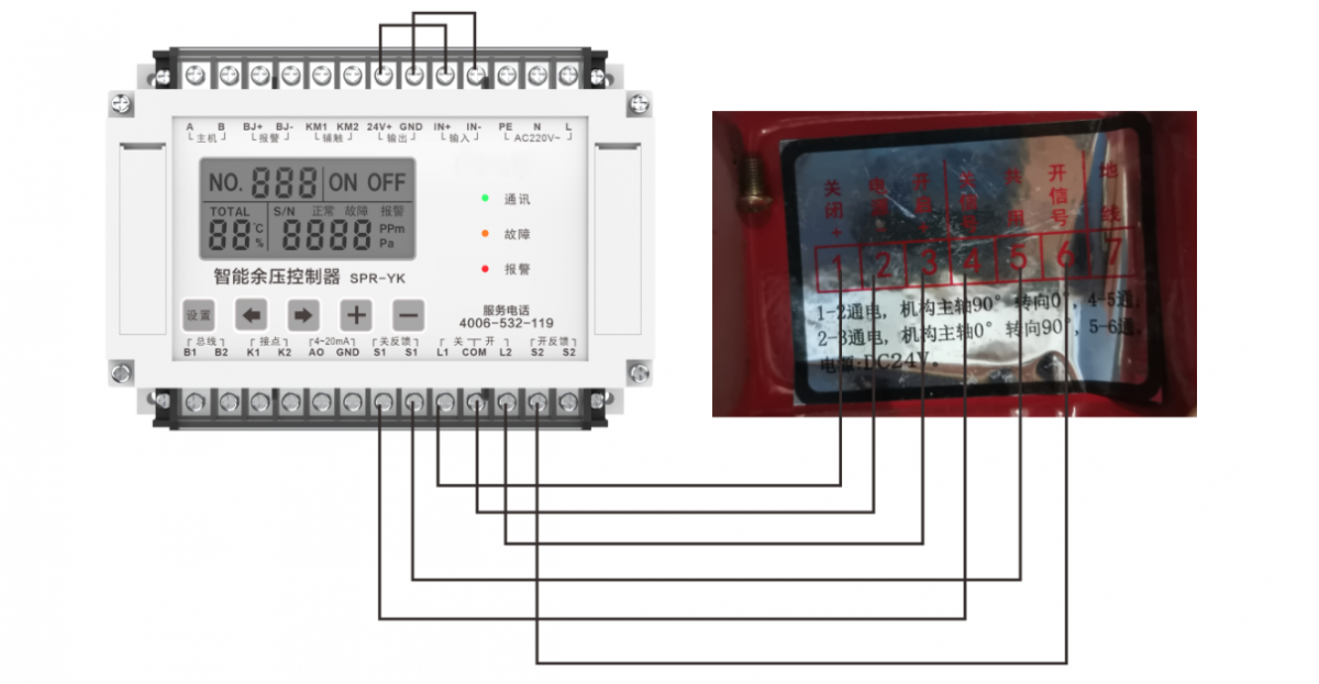
Key points to note include:
The "Input" (IN+/IN-) terminals on the top of the pressure relief controller must be connected to a power source that matches the actuator's operating voltage. In this example, the electric actuator operates at DC24V, so the controller's built-in DC24V output is connected, paying attention to the polarity. If the actuator is AC220V, the "Input" should be connected to the corresponding AC220V.
In the 6-line actuator terminal block, the feedback signal shares a common terminal. This shared terminal can be connected to either the right terminal of the "OFF feedback" (S1 S1) or the "ON feedback" (S2 S2) in the excess pressure controller. As shown in the figure, the common terminal of the actuator feedback is connected to the right "S1" terminal of the "OFF feedback."
The wiring methods at the remaining locations remain unchanged.
