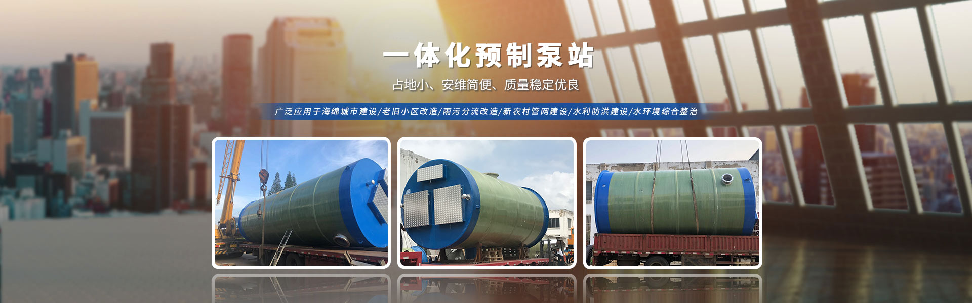

Based on the installation dimensions provided in the pump's general layout and manual, the foundation should be cast and the position of the anchor bolts determined. Generally, it is not advisable to alter the import direction. The foundation surface should be leveled using a level, and the pump should be mounted on the foundation after the cement has cured. The alignment of the motor shaft and the pump shaft should be within ±0.2mm of coaxiality; if their axes do not align, it can cause vibration, leading to bearing overheating and potentially damaging the pump.
Pump intake and discharge pipelines for secondary water supply equipment should have their own supports; generally, it is not allowed for the pump body to bear the weight of the pipeline. When the pump is operating in reverse tank mode, the bottom valve can be omitted; however, a control valve and a filter unit should be installed on the intake pipeline to prevent debris from entering the pump. When the pump is installed above the liquid level, a bottom valve should be fitted at the intake pipe end, with the throat area of the bottom valve being greater than fifty percent of the intake pipe cross-sectional area. It is crucial to thoroughly clean any debris, such as weld slag or metal shavings, from the pipeline before pump installation to prevent them from being吸入 during startup and causing accidents.
The sleeve's inner surface features a double-threaded design, with any cross-section being an elongated circle. Both ends are semicircles with a radius of R (equal to the bolt section radius), and the middle section is a straight line segment 4e in length. Any cross-section of the sleeve is an identical elongated circle, but they are offset by an angle from each other. After the bolt is inserted into the sleeve, closed compartments are formed between the bolt surface and the sleeve's internal threaded surface. Additionally, any cross-section is divided into two upper and lower crescent-shaped work chambers. As the bolt rotates, the volume of the chamber closest to the intake chamber gradually increases, creating a vacuum. Under the force of the pressure difference, liquid is drawn into the work chamber. As the bolt continues to rotate, the work chamber volume keeps increasing until it seals, pushing the liquid along the axial direction into the discharge chamber. At the same time, the upper and lower work chambers alternately cycle, intake and discharge liquid, thus continuously pushing the liquid from the intake chamber to the discharge chamber along the axial direction.
