


- AllProduct Category
-
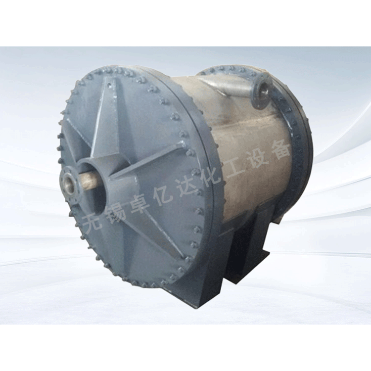
Spiral Plate Heat Exchanger
Heat Exchanger Condensing Equipment
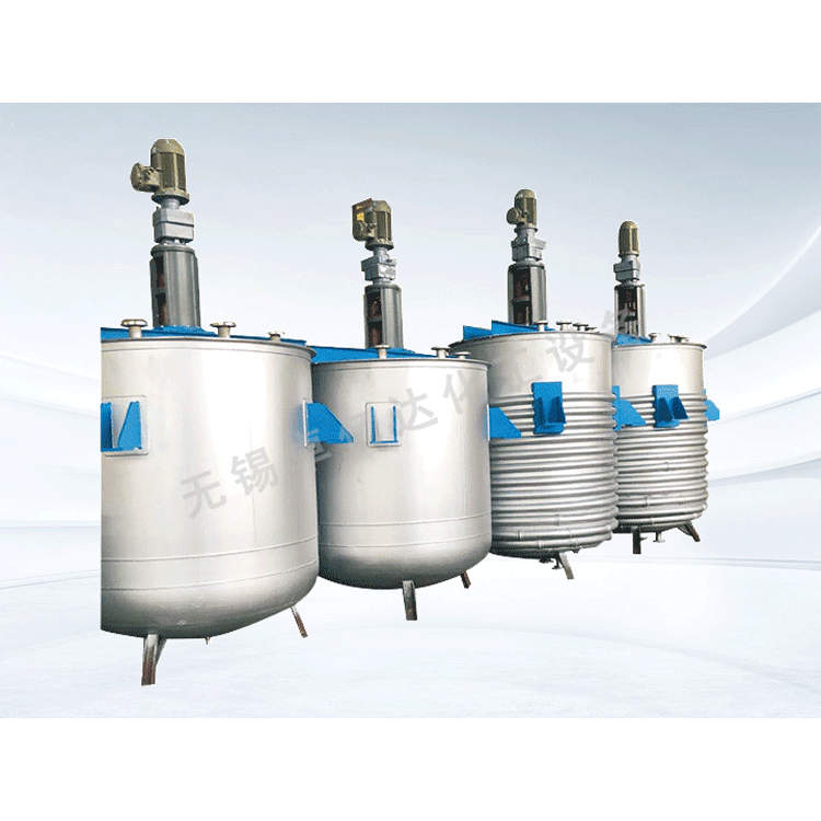
Reactor Mixing Equipment
Tower/Tank Equipment
Other Chemical Equipment


详情描述
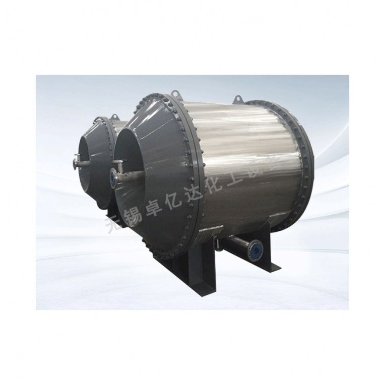
Type III Detachable Horizontal Spiral Plate

Structural Features
1. High thermal efficiency
The Type III removable helical plate heat exchanger features helical channels, where the fluid flows inside. Fixed distance columns or stamped distance bubbles are welded to the helical plates to maintain the width of the channels. Under the centrifugal force of the spiral flow cloud, the fluid can experience turbulence at a lower Reynolds number. Considering that the pressure drop should not be too great, it is important to rationally select the channel width and fluid velocity. During design, it is generally advisable to choose a higher velocity (the allowable design velocity is about 2m/s for liquids and about 20m/s for gases), which can enhance the dispersion of the fluid and improve contact, thereby benefiting the heat transfer efficiency of the helical plate heat exchanger. In recent years, many domestic units have conducted comparisons of heat transfer coefficients between helical plate and tubular heat exchangers. For example, an auxiliary ammonia condenser for a refrigerator, which originally used a heat exchanger with an area of F=30m², was replaced with a Type III removable helical plate heat exchanger with an area of F=75m², resulting in a doubled efficiency. Similarly, a heater under an ammonia synthesis tower in a small fertilizer plant, which previously had a tubular structure with an area of F=30.9m², was replaced with a Type III removable helical plate heat exchanger requiring only F=15.5m², leading to a corresponding doubled efficiency.
2. Efficiently utilizes fluid head loss
Fluids in the Type III removable spiral plate heat exchangers, despite lacking sharp changes in flow direction and pulsations, exhibit higher fluid resistance compared to shell-and-tube heat exchangers due to the longer spiral channels and fixed-distance columns welded to the spiral plates. However, with uniform spiral flow within the channels, the main resistance occurs from friction between the fluid and the spiral plates and collisions with the fixed-distance columns, which can induce turbulence. This increases the heat transfer coefficient, allowing the Type III removable spiral plate heat exchangers to effectively utilize fluid pressure head losses.
3. Non-clogging
In recent years, numerous studies have focused on the issue of fouling in heat exchangers, as fouling significantly impacts their heat transfer efficiency. In Type III removable spiral plate heat exchangers, since the medium flows through a single channel and the allowable velocity can be higher than in other types of heat exchangers, fouling is less likely to accumulate. If fouling does deposit in a channel, the cross-sectional area of that channel decreases, and with a certain flow rate, a reduction in area results in a corresponding increase in local velocity, which cleans the fouled area. In shell-and-tube heat exchangers, if one heat exchange tube has fouling, the local resistance of that tube increases, limiting the flow and reducing the velocity, causing the medium to分流 to other tubes. This re-balances the resistance across each tube in the heat exchanger, making the velocity of the fouled tube progressively lower, more prone to further fouling, and eventually leading to complete blockage. In chemical and oil refineries, the tubes of shell-and-tube heat exchangers often accumulate fouling, leading to blockage. However, in Type III removable spiral plate heat exchangers, with their self-cleaning action, the rate of fouling formation is about 1/10 that of shell-and-tube heat exchangers.
When encountering blockages, overseas commonly use acid washing or hot water cleaning, while in China, the majority opt for steam blowing to clean, which is both convenient and efficient compared to hot water cleaning.
4. Our heat exchangers utilize low-temperature heat sources and can control the outlet temperature. To enhance the heat transfer efficiency of the Type III removable spiral plate heat exchanger, an increased driving force for heat transfer is required. When both fluids operate in a full counter-current flow in the spiral channels, the logarithmic mean temperature difference between the fluids is greater, which is beneficial for heat transfer. Analyzing the empirical data from the heat exchanger design, the Type III removable spiral plate heat exchanger allows for a minimum temperature difference that is low, enabling heat exchange even when the temperature difference between the two fluids is only 3℃. Due to the lower allowed temperature difference, countries worldwide utilize this type of heat exchanger for recovering low-temperature thermal energy.
Type III removable spiral plate heat exchanger features two longer, evenly distributed spiral channels, allowing for uniform heating and cooling of the medium, thus enabling control over its outlet temperature.
5. Compact structure
A 1.5m diameter and 1.8m width Type III removable spiral plate heat exchanger, with a heat transfer area of up to 200m², and a heat transfer area per unit volume approximately three times that of a shell-and-tube heat exchanger.
6. Sealed structure is reliable
Currently, the Type III removable spiral plate heat exchanger we use features sealed ends with welding (irreversible) and end cover clamping (removable). The irreversible seal ensures welding quality while preventing internal leakage between the two media. The removable ends are clamped with end covers, which have an integral sealing plate. As long as the two ends of the spiral channels are smoothly machined, it can prevent fluid from one side from bypassing to the other side.
7. Small temperature difference stress
The III-type removable spiral plate heat exchanger features allow for expansion. Due to its two longer spiral channels, the spiral plates can extend and contract like a spring inside a clock when heated or cooled. Each turn of the spiral has one side for hot fluid and the other for cold fluid, with the outer turns exposed to the atmosphere. The temperature difference between the spirals is not as pronounced as the temperature difference between the tubes and shell in a shell-and-tube heat exchanger, thus avoiding significant temperature difference stress.
Technical Specifications


