

- AllProduct Category
-
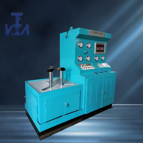
YFA-L Type Vertical Top-Pressure Valve Hydraulic Test Bench
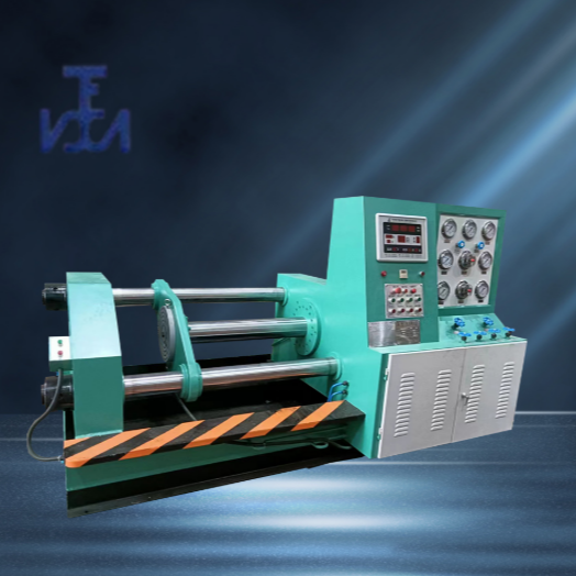
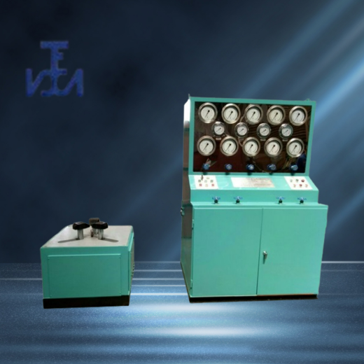
YFA-H Type Pressure-Actuated Valve Hydraulic Test Bench
YFA-F Type Valve Hydraulic Test Bench
YFA-FQ Submerged Suction Pressure Valve Hydraulic Test Bench
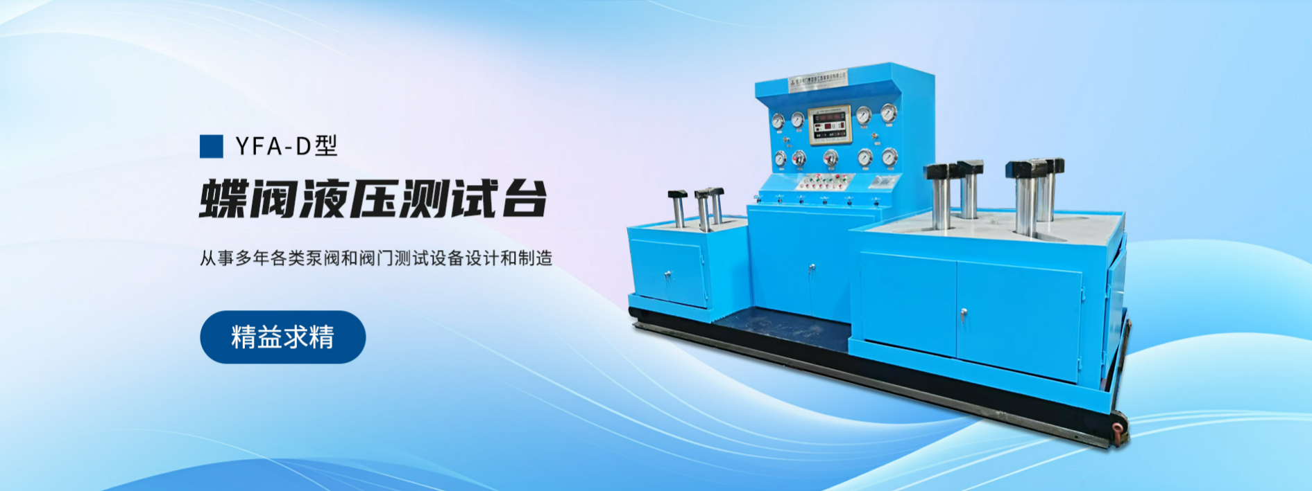
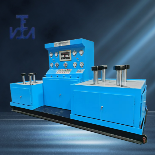
YFA-D Type Butterfly Valve Hydraulic Test Bench
YFA-A Type Safety Valve Hydraulic Test Bench
Planetary Grinder with DOM Design


详情描述
I. Overview
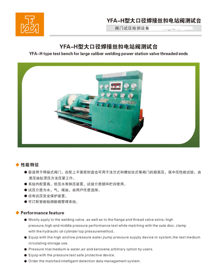
YFA-H Type Pressure-Actuated Hydraulic Valve Test Bench, which is based on our company's years of experience in producing valve testing equipment, strictly adheres to GB/T13927-2008 "General Valve Pressure Test" and JB/T26480-2011 "Testing and Inspection of Valves."American Petroleum Institute StandardDesign and production are required to meet the test pressure requirements of specifications such as API598.
Widely applied to high, medium, and low-pressure direct-connected flanged and焊接 valves, pressure seal performance and shell strength pressure tests; suitable valve types include gate valves, stop valves, check valves, ball valves, etc. It is used by valve manufacturers, petrochemical industries, hydropower stations, etc.Natural GasIdeal valve testing and inspection equipment for industries such as pipeline fittings, wastewater treatment plants, and valve repair stations.
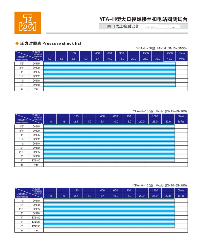
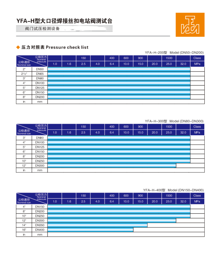
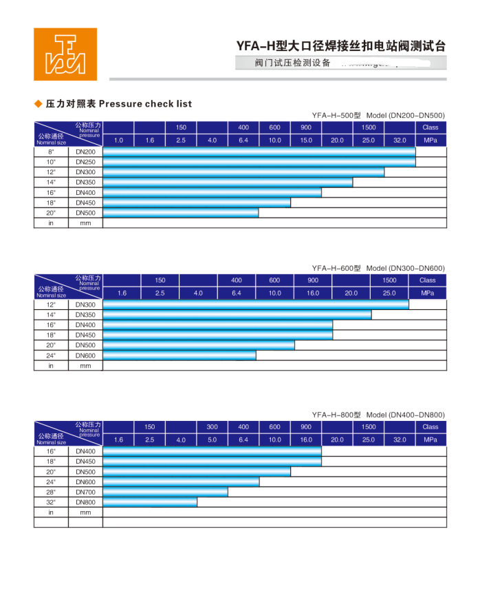
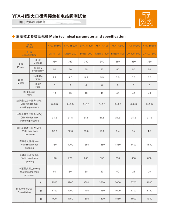
Spec Range: Nominal Pipe Size 15-mm to 1000-mm
Section 3: Pressure Range: Nominal Pressure 1.6-42.0 (MPa) / 150-2500 (Class)
Four: Performance Features:
1、This unit integrates a hydraulic, mechanical, electrical system, pressure supply device, and a medium storage and circulation water tank into one. The entire testing process is automatically controlled and executed by hydraulic and electrical components.The complete hydraulic system employs the most reliable hydraulic control form currently available. The clamping force acting on the tested valve can be infinitely adjustable in pressure, effectively preventing damage to the tested valve. The operation ensures sensitive actuation and precise positioning throughout its use.Well-structured, fully functional, stable performance, easy to operate, broad application range, and high level of automation.
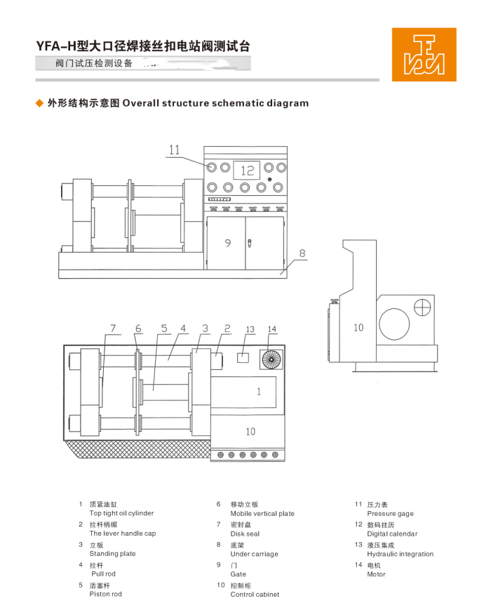
2. The workbench bridge on both sides is connected by two rods and secured with a handle cap lock. A movable work plate is installed in the middle, allowing for forward and backward movement. The structure length is not restricted during valve testing, making it suitable for sealing tests and strength pressure tests of both direct passage flanged and welded valves. During valve testing, either a bevel end face or a flange plane is used for sealing. The top pressure cylinder directly drives the central moving plate to the valve face for tightness, with the clamping force able to...Continuous pressure regulation or automatic boost to the desired pressure level via button actuation.
3. The test bench features a dual-system for air and water, with both bidirectional pressure intake and release, and is equipped with a leak testing port. The system is pre-configured with high and low-pressure water pumps, allowing for direct hydrostatic testing. The high and low-pressure water pumps come with automatic control functionality. The gas source is user-supplied, and the liquid testing medium can be recycled and stored for use, offering energy-saving, environmentally friendly, low cost of investment, and high work efficiency.
4. The equipment features reliable safety protection measures, with an interlocked linkage function in the locking mechanism. When pressure is present in the valve cavity, the locking cylinder's tensioning action is locked until the pressure within the valve cavity is fully released, at which point the button can be released. This prevents accidental operation and ensures safe use.
V. Usage Instructions:
1. Fill the hydraulic system oil tank with 30#-46# hydraulic oil or 20# mechanical oil; the oil level must not be below the lower limit of the oil gauge.
2. Power on, press the oil pump start button, and check if the motor is rotating in the correct direction (clockwise).
Adjust the hydraulic system pressure to 5.0 MPa for normal operation.
4. Select a sealing disk suitable for valve testing and install it on both work plates.
4. Engage the point-of-action cylinder's tightening button, move the middle seal plate to closely seal against the valve end face, based on the valve diameter and pressure.Adjust the pressing pressure according to the (Pressure Requirement Chart for Cylinder Clamping). For pressures exceeding the pump source by more than 5.0 MPa, press the (Cylinder Pressure Boost) button to increase the pressure to the required level.The boost button can be pressed multiple times, with each interval approximately 3-5 seconds, and the maximum pressure is 30MPa.
Section 6: Gas Pressure TestRight-justified
1. Gas tightness pressure test: Valve mounting complete (1)Shut off: Total inlet valve → Left inlet valve → Right pressure relief valve → Test butterfly valve. (2) Open: Right pressure gauge switch → Right inlet valve → Inject gas into the total inlet valve. Close (total inlet valve) when the air pressure reaches the required pressure value. (3) Enter the pressure holding timing phase. When the pressure holding time is up, open the leak detection switch to check for bubble leakage at the leak detection port and whether the pressure gauge shows pressure drop to judge if the valve's sealing performance is qualified.
2. Gas Strength Pressure Test: Based on the sealed test fixtureBased on the valve port diameter and pressureRefer to the (cylinder clamping pressure reference table) to adjust the clamping pressure.(1)Shut off: Main inlet valve → Left and right pressure relief valves → Leak detection switch. (2) Open: Valve under test → Left and right pressure gauge switches → Inject gas into the main inlet valve. Close (the main inlet valve) when the pressure reaches the required value, and spray foam on the valve body surface. (3) Proceed to the pressure-holding timing phase. Upon expiration of the pressure-holding time, check for bubble leakage at the valve connection seals and the valve body surface, and verify the pressure gauge for pressure drop to assess the valve's strength performance. (4) After testing, open the pressure relief valve, exhaust the pressure, and remove the valve.
Section 7: Water Pressure Test: Right as column
1. Water Seal Pressure Test:
Similarly, pressure-sealed test fixture, (1)Set the low-pressure pump electrical contact pressure to 1.8 (Mpa). Set the electrical contact pressure gauge (with sealed pressure listed at 2.5MPa, adjust the red pointer of the electrical contact pressure gauge to 2.5MPa). (2) Close: Total intake valve → Left and right pressure relief valves → Right pressure gauge switch → Valve under test. (3) Open: Total intake valve → Left and right intake valves → Left leak detection switch.
(4) Start the low-pressure water pump to fill the system until water exits through the (left leakage detection switch), then close the (left water inlet valve). When the low-pressure water pressure reaches the set value of 1.8 (MPa), it indicates that the right valve cavity is fully filled with water, and the low-pressure pump will automatically stop. The high-pressure pump will then automatically start to supply pressure. When the high-pressure water reaches the set value of 4.0 (MPa), the high-pressure pump will automatically stop, and the pressure maintenance timer (such as 2 minutes/client-defined) will begin. Check for leaks at the left leakage detection port and any pressure fluctuations on the gauge to determine if the valve's pressure strength is up to standard.
2、Water Strength Pressure Test:
Similarly, the pressure intensity pressure test valve mounting is all completed, (1)Set the low-pressure pump electrical contact pressure to 1.8 (Mpa). Adjust the electrical contact pressure gauge (use 4.0MPa as an example for strength pressure) by moving the red pointer to 4.0MPa. (2) Close: Total inlet valve → Left and right pressure relief valves → Left and right leak detection switches → Left and right pressure gauge switches. (3) Open: Total water inlet valve → Valve under test. (4) Start the low-pressure pump to fill water. When the low-pressure water pressure reaches the set value of 1.8 (MPa), it indicates that the valve cavity is full of water, and the low-pressure pump will automatically stop. The high-pressure pump will then automatically start to supply pressure. When the high-pressure water reaches the set value of 4.0 (MPa), the high-pressure pump will automatically stop, and the pressure holding time (e.g., 2 minutes/client-defined) will begin. Check for any leaks at the valve connection surfaces and the valve body, and ensure the pressure gauge is stable, to determine if the valve's strength pressure test is合格. (5) After testing, exhaust the pressure, release the button, and remove the valve.
Section 8: Usage Precautions and Requirements:
1. The site should be arranged in a level indoor space, properly leveled, with concrete footings secured. The operating environment temperature should be between (1-40)℃; ideal for use in a normal temperature or heated workshop during winter. Surroundings should be free of high concentrations of dust and corrosive gases. Avoid proximity to grinding wheel machines and poorly ventilated areas. Ensure good ventilation; leave at least 1m of space around the installed equipment for ease of operation and maintenance.
2. Operators must undergo professional training before starting work, adhere to standard procedures, and strictly prohibit the use of equipment beyond specifications or pressure. Non-professionals are advised not to operate.
3. Operators are strictly prohibited from leaving their posts during the pressure testing process. They must continuously monitor the pressure to prevent it from exceeding safe levels.
4. After the test is completed, the pressure must be released to zero before the clamps can be released. The power should be disconnected when not in use.
5. The moving parts of the testing bench should be frequently lubricated to maintain cleanliness and smooth operation.
6. Use 46# anti-wear hydraulic oil (for temperatures below 0°C, use antifreeze 46# anti-wear hydraulic oil), and ensure the oil level does not fall below the indicator. Regularly check the oil level and hydraulic oil; after one year of use, it should be cleanedWash OilBox, replace with new oil.
7. Water source must be clean and free of impurities. If water quality deteriorates, it must be replaced promptly. Add new rust inhibitor powder to meet testing requirements. To ensure that test valves are not corroded, it is usually necessary to add rust inhibitor powder regularly to the circulating water tank to prevent rusting of the medium water affecting the normal operation of pipes, pumps, and check valves.
Note: Common anti-rust powders include:Sodium nitriteSodium sulfonate, sodium benzenesulfonate (non-toxic, powdered form).
8. The equipment work surface should be kept clean, and there should be no debris between the test valve flange and the pressure testing blind plate.