

- AllProduct Category
-
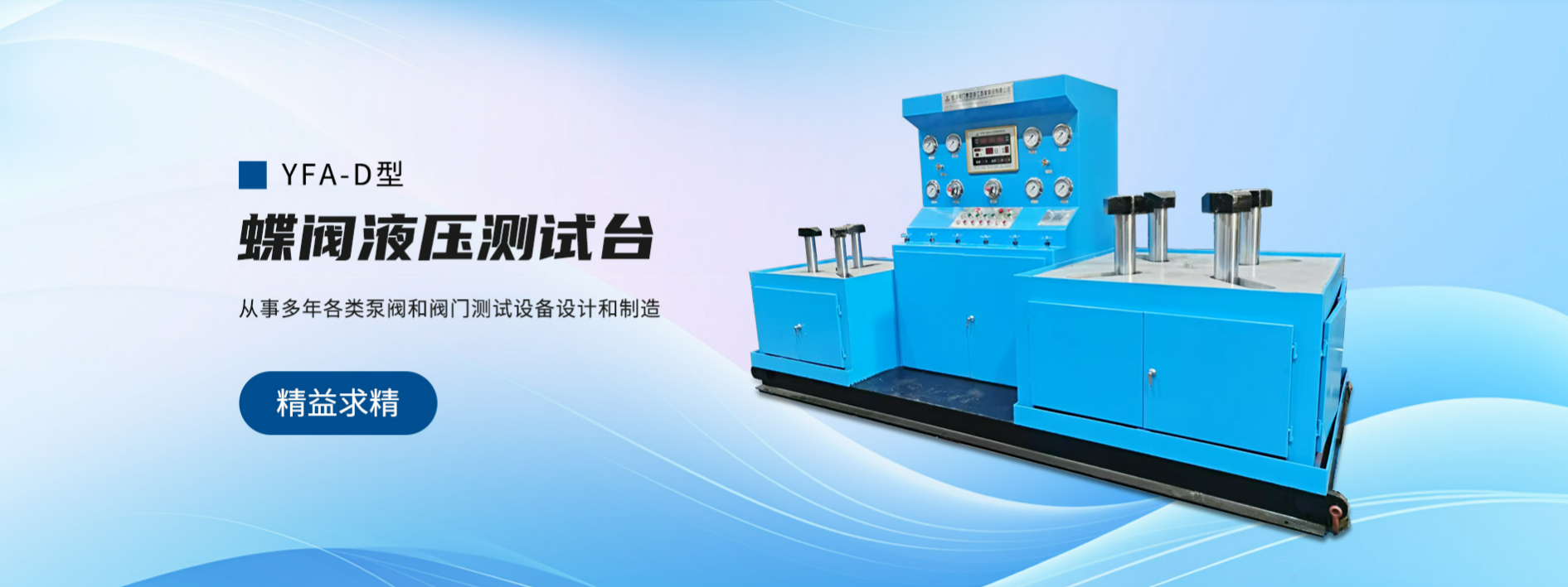
YFA-L Type Vertical Top-Pressure Valve Hydraulic Test Bench
YFA-H Type Pressure-Actuated Valve Hydraulic Test Bench
YFA-F Type Valve Hydraulic Test Bench
YFA-FQ Submerged Suction Pressure Valve Hydraulic Test Bench
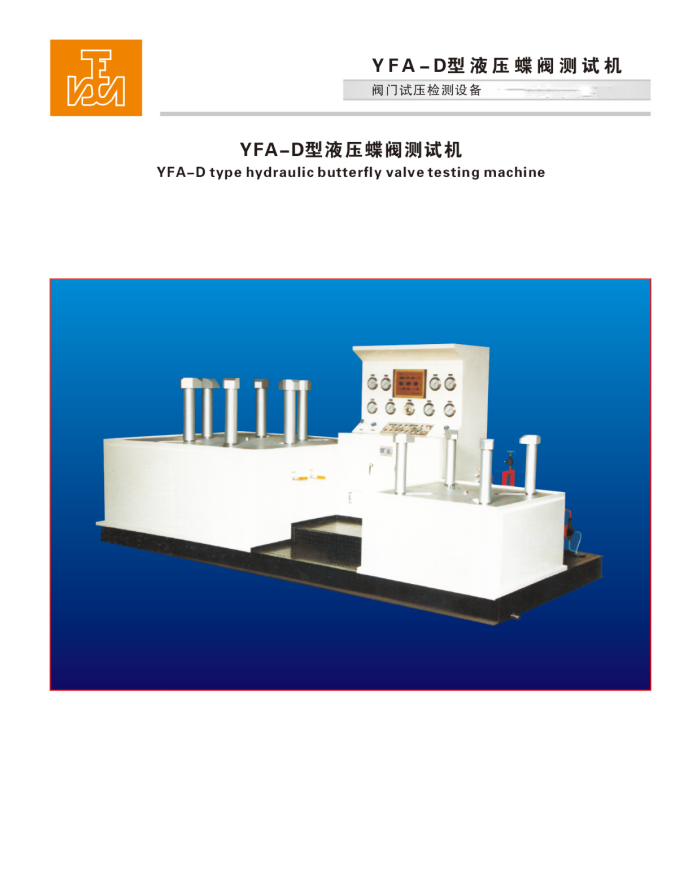
YFA-D Type Butterfly Valve Hydraulic Test Bench
YFA-A Type Safety Valve Hydraulic Test Bench
Planetary Grinder with DOM Design


详情描述
I. Product Overview:
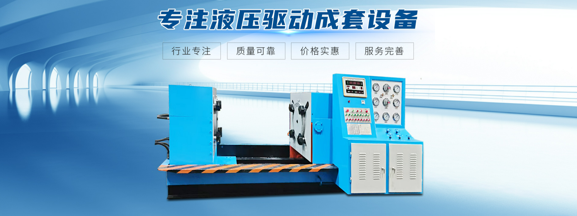
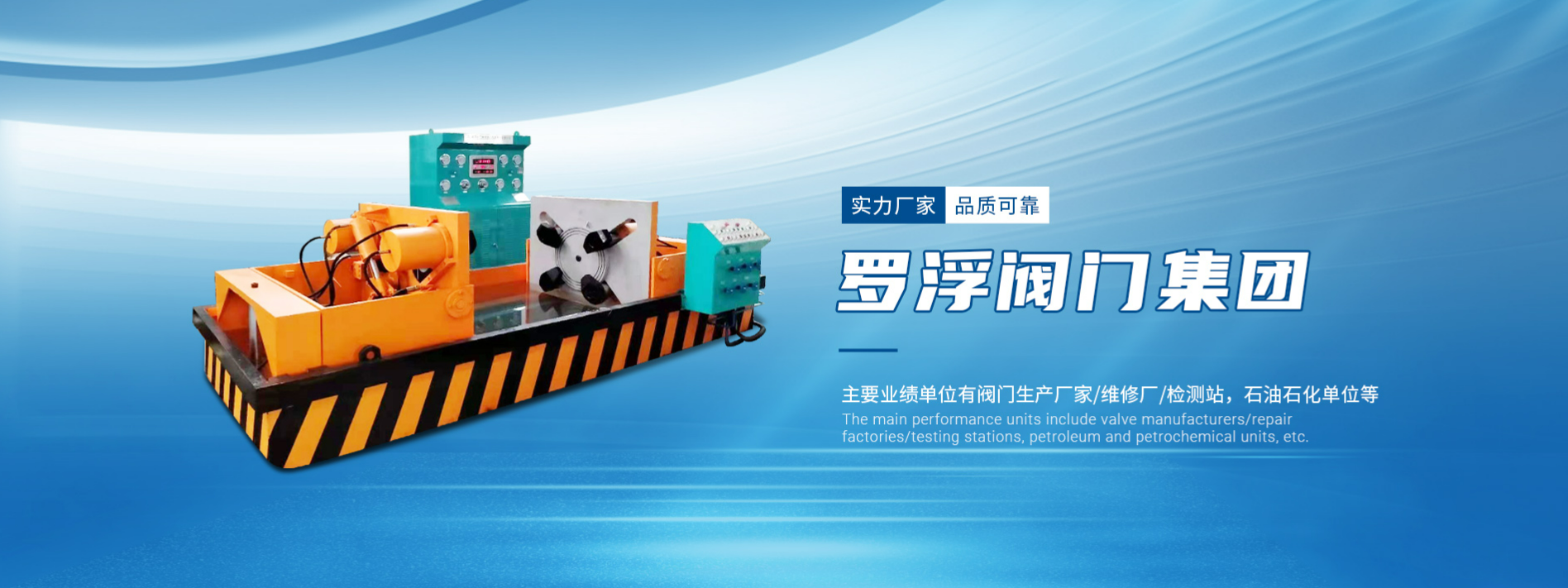
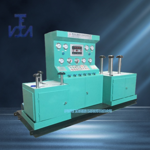
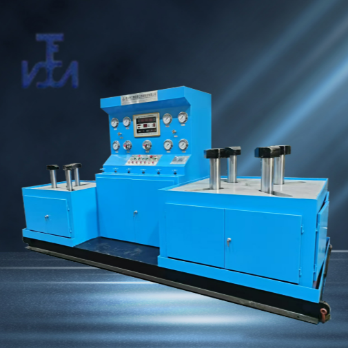
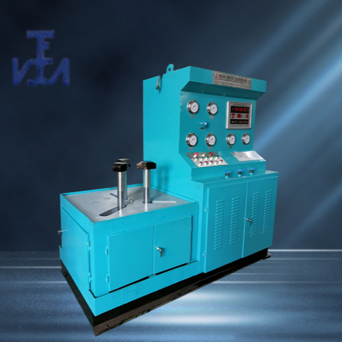
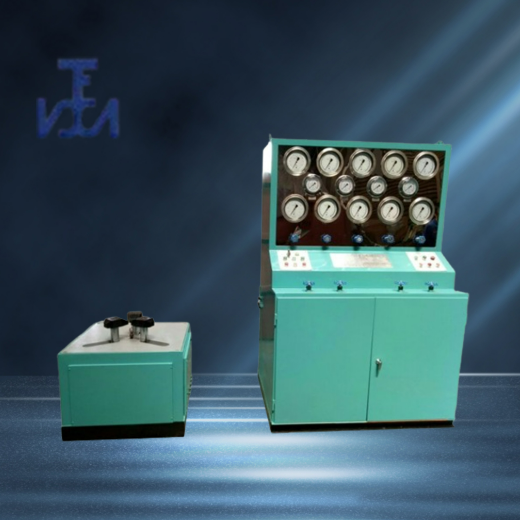
YFA-D Type Butterfly Valve Hydraulic Test Bench, a specialized testing equipment for butterfly valves. Based on years of experience in producing valve testing equipment, the company strictly adheres to GB/T13927-2008 "General Valve Pressure Test" and JB/T26480-2011 "Testing and Inspection of Valves."American Petroleum Institute StandardDesign and production in compliance with API 598 and other specifications require test pressure.
This unit integrates a hydraulic, mechanical, electrical system, pressure supply unit, and medium storage circulating water tank. The entire testing process is automatically controlled and executed by hydraulic and electrical components. It boasts advantages such as a rational structure, comprehensive functions, stable performance, ease of operation, and high degree of automation. It is widely used in high, medium, and low-pressure testing of butterfly valves for pressure-sealing performance and shell strength, applicable to valve types such as flanged and clamped butterfly valves, knife gates, etc. It is suitable for valve manufacturers, the petrochemical industry, hydropower stations, and more.Natural GasIdeal valve testing and inspection equipment for industries such as pipeline components, wastewater treatment plants, and valve maintenance stations.
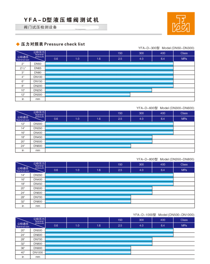
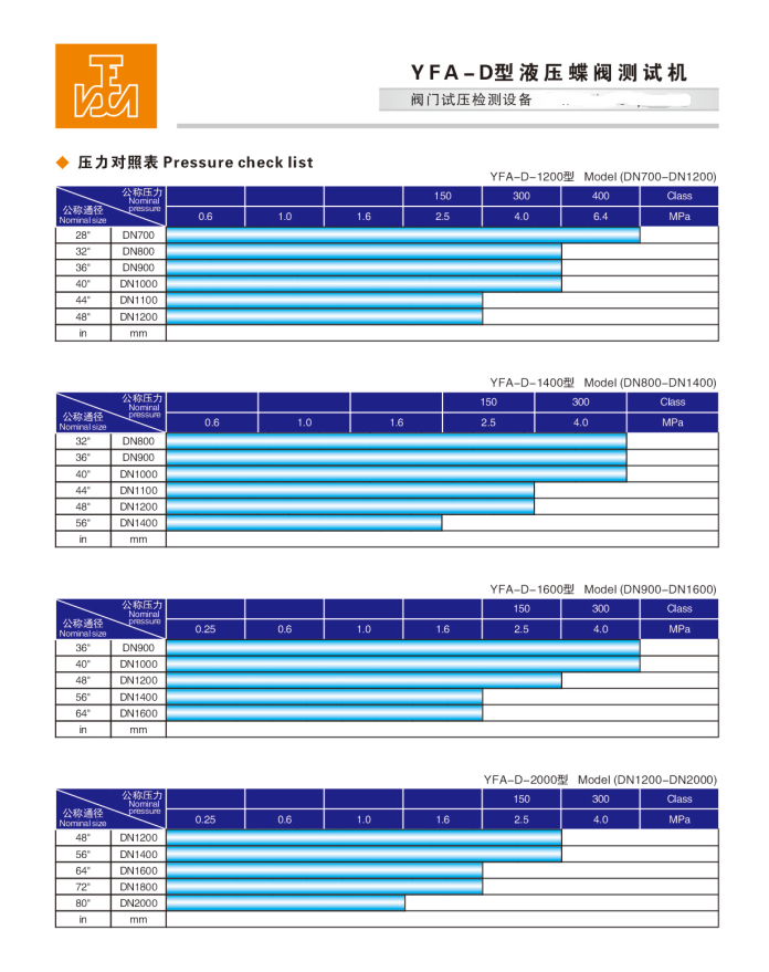
II. Specification Range:
Single Station: 50-2200mm
Three, Pressure Range: 0.6-10.0 (MPa) / 150-600 (Class)
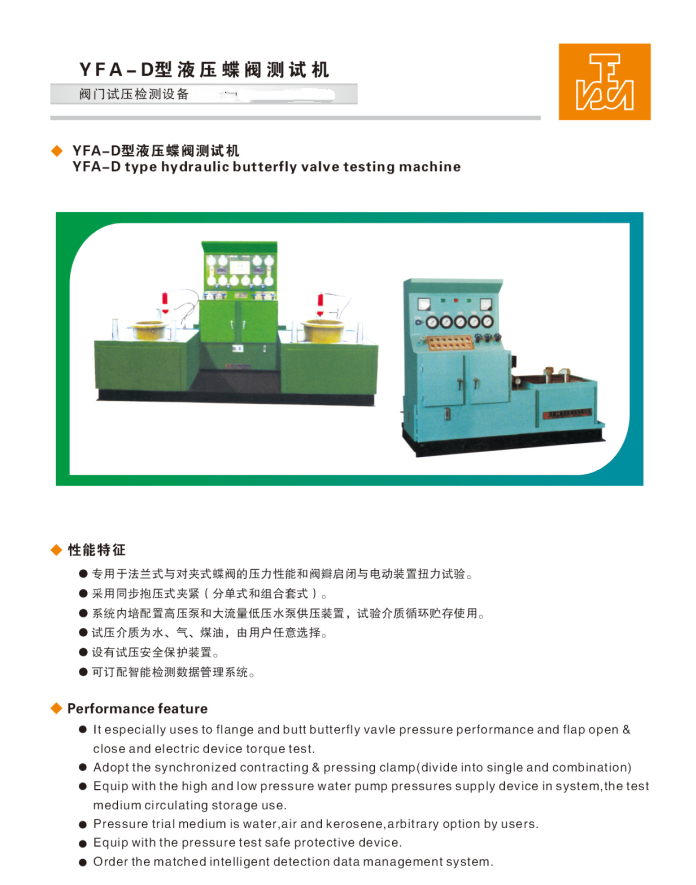
IV. Performance Features:
Suitable for direct-connection flanged and wafer butterfly valves, featuring face-to-face flange sealing. The workbench is equipped with a removable hydraulic clamping system, which can be uniformly installed. It can automatically synchronize and adjust the position of the clamping jaws for various valve specifications, achieving automatic centering and positioning. During valve testing, the hydraulic clamping jaws automatically clamp the flange face of the valve, with adjustable clamping force, exerting no external force on the valve being tested. The clamping process is fully controlled by integrated buttons, executed by hydraulic components.
The equipment is equipped with high and low-pressure water pumps, allowing for direct hydrostatic testing. It features a dual-air-water system, with the gas source to be provided by the user.
Principle and Operating Method of Butterfly Valve Hydraulic Test Bench
I. Principle of Operation for YFA-D Type:
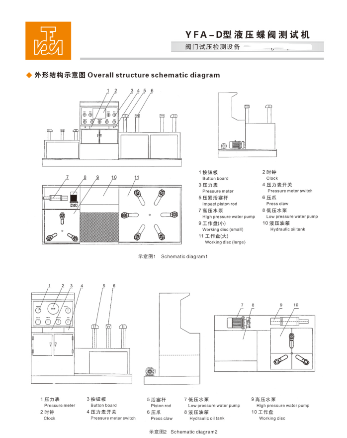
YFA-D Type Butterfly Valve Hydraulic Valve Test Bench is a specialized testing equipment for butterfly valve sealing performance and housing strength pressure tests. The machine integrates hydraulic system assembly, clamping cylinders, mechanical components, high and low-pressure pump pressure supply units, pressure gauges, valve control switches, clamping worktable, electrical control system, and medium storage and circulation water tanks into one.A hydraulic clamping cylinder is installed on the workbench to evenly distribute the clamping force, directly driving the clamping jaws to clamp the butterfly valve's flat surface for testing, ensuring even distribution of force among the jaws for reliable clamping. The radial movement function of the clamping jaws is achieved using a cylinder and a linkage, allowing synchronous radial movement of all jaws. The clamping cylinder is regulated by a hydraulic分流er to synchronize the axial clamping cylinders. This ensures testing of butterfly valves of different sizes and diameters. During the sealing test of the butterfly valve, a sealing disc compatible with the test valve is mounted on the machine, then the butterfly valve is placed on the sealing disc and directly clamped onto the flange surface by the hydraulic jaws. This allows for the injection of test medium. During the test process, it is possible to visually inspect for leaks or bubbles inside the butterfly valve. For strength tests, simply add a sealing cover plate to the upper surface of the butterfly valve. This equipment is equipped with high and low-pressure liquid supply pumps and can directly conduct liquid pressure tests. The liquid medium can be circulated and stored for use, preventing rust and corrosion of check valves and affecting the normal operation of the equipment. Rust inhibitors must be added to the water.
II. Usage Instructions:
1. Fill the hydraulic system oil tank with 30#-46# hydraulic oil or 20# mechanical oil; the oil level must not be below the lower limit of the oil gauge.
2. Power on, press the oil pump start button, check if the motor is rotating in the correct direction (counterclockwise).
3. Adjust the hydraulic system pressure to 5.0 MPa to proceed with normal operation.
4. Retract the point action clamp to a position greater than the outside diameter of the tested butterfly valve flange.
5. Place the test butterfly valve at the center of the workbench's sealing disk.
6. Release the point action gripper to a height above the tested butterfly valve.
7. Advance the point-clamping jaw to the required position for the test butterfly valve flange.
8. Engage the point-action clamp to securely grip the test butterfly valve flange surface; conduct the butterfly valve sealing test.
9. Place a sealing cover plate on the flat surface of the butterfly valve flange, clamp the sealing cover plate securely with the clamps, and then perform the strength test of the butterfly valve shell.
(6) Adjust the clamping pressure according to the (Pressure Chart for Cylinder Clamping). For pressures exceeding the pump source by more than 5.0 Mpa, press the (Clamp Pressure Increase) button to increase the pressure to the required clamping level.The boost button can be pressed multiple times, with each interval being approximately 3-5 seconds; the maximum pressure is 30MPa.
Section 3: Gas Pressure Test:
1. Gas seal pressure test: Valve mounting complete (1)Shut off: Total inlet valve → Relief valve → Test butterfly valve. (2) Open: Pressure gauge switch → Total inlet valve to inject gas. Close (inlet valve) when the air pressure reaches the required pressure value, and add water inside the butterfly valve cavity. (3) Enter the pressure-holding timing phase. Upon reaching the pressure-holding time, check for bubble leakage on the valve sealing surface and body surface, and if the pressure gauge shows a pressure drop to determine if the valve's sealing performance is up to standard.
2. Gas Strength Pressure TestValve mounting complete, (1)Close: Total inlet valve → Pressure relief valve. (2) Open: Test butterfly valve → Pressure gauge switch → Total inlet valve to inject gas. Close (total inlet valve) when the air pressure reaches the required pressure value. Spray foam agent on the butterfly valve body surface (3) Enter the pressure-holding timing phase. Upon the completion of pressure-holding time, check for bubble formation at the valve connection seal surfaces and valve body surface, and pressure gauge drop to judge if the valve's strength performance is qualified. (4) After testing, open the pressure relief valve, exhaust the pressure, and remove the butterfly valve.
Section 4: Hydrostatic Test
1. Water-tight pressure test completed, valve mounting all done, (1)Set the low-pressure pump electrical contact pressure to 1.8 (Mpa). Adjust the electrical contact pressure gauge (with a sealed pressure of 1.6MPa as a reference) by setting the red pointer to 2.5MPa. (2) Close: Main inlet valve → Pressure relief valve → Pressure gauge switch → Test butterfly valve. (3) Open: Main water inlet valve → Test valve.
(4) Start the low-pressure water pump. When the low-pressure water pressure reaches the set value of 1.8 (MPa), it indicates that the valve chamber is already filled with water. The low-pressure pump will automatically stop, and the high-pressure pump will automatically start to supply pressure. When the high-pressure water reaches the set value of 2.5 (MPa), the high-pressure pump will automatically stop, and enter the pressure holding timing period (such as 2 minutes/client-defined). Check for any leaks on the valve sealing surface and body, and ensure the pressure gauge is stable, to confirm the valve's pressure test for strength is合格.
2、Water strength pressure test completed, valve fixture set up, (1)Set the low-pressure pump electrical contact pressure to 1.8 (MPa). Adjust the electrical contact pressure gauge (use 4.0 MPa as the reference point) by moving the red pointer to 4.0 MPa. (2) Close: Total inlet valve → Pressure relief valve → Pressure gauge switch. (3) Open: Total inlet water valve → Valve under test. (4) Start the low-pressure pump. When the low-pressure water pressure reaches the set value of 1.8 (MPa), it indicates that the valve cavity is filled with water. The low-pressure pump will automatically stop, and the high-pressure pump will automatically start to supply pressure. When the high-pressure water reaches the set value of 4.0 (MPa), the high-pressure pump will automatically stop, and enter the pressure holding timing period (e.g., 2 minutes/client's specification). Check for any leaks at the valve connection surfaces and the valve body, and ensure the pressure gauge is stable, to confirm the valve's strength pressure test is合格. (5) After testing, exhaust the pressure, release the button, and remove the butterfly valve.
Section 6: Usage Precautions and Requirements:
1. The site should be arranged in a level indoor space, properly leveled, and the base fixed with concrete. It is suitable for use in a temperature range of (1-40)℃ in a normal or heated workshop during winter. Surroundings should be free from high concentrations of dust and corrosive gases. Avoid locations near grinding wheels or polishing machines with poor conditions. Ensure good ventilation. Leave at least a 1m space around the equipment installation for ease of operation and maintenance.
2. Operators must undergo professional training before starting work, adhere to standard procedures, and strictly avoid exceeding specifications or pressure. Non-specialists are prohibited from operating.
3. Operators are strictly prohibited from leaving their posts during the pressure testing process. They must continuously monitor the pressure to prevent it from exceeding safe levels.
4. After the test is completed, the pressure must be released to zero before the clamps can be released. The power should be disconnected when not in use.
5. Regularly add lubricant to all moving parts of the testing bench to maintain cleanliness and smooth operation.
6. Use 46-grade anti-wear hydraulic oil (for temperatures below 0℃, use antifreeze 46-grade anti-wear hydraulic oil). The oil level must not be below the indicator's lower limit. Regularly check the oil level and hydraulic oil; after one year of use, it should be drained and replaced.Wash OilBox, replace with new oil.
7. Water source must be clean and free of impurities. If water quality deteriorates, it should be changed promptly. Add new rust-proof powder to meet testing requirements. To ensure that test valves are not corroded, it is typically necessary to add rust-proof powder regularly to the recirculating water tank to prevent rusting of the medium water affecting the normal operation of pipes, pumps, and check valves.
Note: Common rust-preventing powders include:Sodium nitrateSodium sulfonate, potassium benzenesulfonate (non-toxic, powdered form).
8. The work surface of the equipment should be kept clean, and there should be no debris between the valve flange being tested and the pressure test blind plate.