
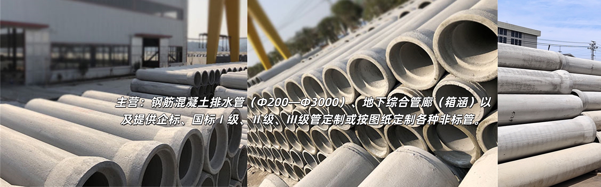
公司主营:Reinforced concrete drainage pipes (Φ200—Φ3000), underground utility tunnels (box culverts), and custom non-standard pipes as per drawings provided.
13645788727
企业资质
Comprehensive Standard for the Entire Installation and Construction Process of Cement Pipe
2025-09-20
The installation of cement pipelines is a crucial step in ensuring the stable operation of the drainage system, requiring strict adherence to standardized procedures from preliminary preparation to final acceptance. Below, we detail the key points of the full installation process of cement pipelines in the order of construction.
Pre-construction preparation phase
Technology and Solution Preparation
Incorporating engineering design drawings, we clearly define the pipeline direction, diameter, burial depth, and gradient, and compile a specialized installation and construction plan. We also mark the construction requirements for key points (such as turns, changes in diameter, and inspection well locations).
Organize technical briefings for construction workers, clearly defining their job responsibilities, construction standards, and safety precautions, ensuring that workers are familiar with the drawings and details of the plan.
2. Tube and Material Preparation
Pipe material selectionQualified pipe materials are procured according to design specifications, inspected individually for appearance (free of cracks, missing corners, exposed steel reinforcement, etc.) and dimensions (diameter, length, and wall thickness in compliance with drawings) before entry. Concrete strength is randomly tested using a rebound meter, and only upon meeting the required standards can the materials be admitted.
Supplementary MaterialsPrepared sealing gaskets (check for elasticity and no damage), specialized lubricants (avoid oily lubricants), sandstone bedding materials (medium particle size, low silt content), backfill soil (must meet compaction requirements), as well as repair epoxies and repair mortars.
3. Equipment and facility preparation
Equipment calibrationEquipped with cranes (with specialized lifting equipment), excavators (for foundation trench excavation), leveling instruments (for slope calibration), compactors/mini rollers (for backfill compaction), sealant installation tools, pipe sealing equipment, etc., pre-inspect the performance of the equipment to ensure smooth operation.
Site ClearanceClear obstacles along the construction route, level the construction site, and designate areas for pipe material storage (which requires leveling and elevation to prevent moisture damage), material storage, and work areas. Prepare temporary drainage facilities to prevent water accumulation on the site.
Section II: Excavation and Foundation Treatment Phase
Excavation surveying and marking out
According to the design plans, locate the pipeline center line and manhole positions using a total station. Mark the excavation boundary lines on either side of the center line, setting control piles every 20-30 meters, and annotate the excavation depth (calculated based on pipe top burial depth, pipe diameter, and bedding thickness).
Excavation of the foundation pit underway
Excavation is conducted in layers using excavators, with depth monitored in real-time using a level to prevent over-excavation. The excavation width must be 30-50cm wider than the pipe's outer diameter to allow for operational space. If the excavation depth exceeds 1.5 meters, the excavation must be sloped according to specifications (slope determined by soil type, e.g., silty clay at approximately 1:0.5) or supported with shoring (such as sheet piles) to prevent the collapse of the foundation pit.
When excavation reaches 10-15cm above the designed elevation, switch to manual cleanup of the base to prevent mechanical disturbance to the subsoil, ensuring a flat base without any bumps, dents, or debris.
3. Foundation Reinforcement Treatment
If the foundation is in its original state of soil and meets the bearing capacity standards (passed the bearing capacity test), it can be leveled directly and a sand and stone cushion layer can be laid. If the foundation is soft soil, silt, or other weak soil types, it is necessary to first replace it with qualified soil material (such as graded sand and stone), compacted in layers (each layer 20cm thick, with compaction not less than 90%), then lay a sand and stone cushion layer 10-20cm thick, compact it with a compactor, ensure the foundation's bearing capacity meets pipeline installation requirements, and prevent subsequent settlement.
III. Core Construction Phase for Pipe Installation
Pipe sections successfully hoisted into position
Using a crane (equipped with specialized lifting devices such as lifting straps and special clamps) to smoothly lift the piping materials, the lifting point must be symmetrical to prevent the piping from tilting or colliding. Gently lower the piping into the foundation pit, arranging it in the installation sequence (from downstream to upstream), aligning the pipe ends of adjacent sections, and leaving a 5-10mm joint gap.
After the piping is placed, wooden wedges are temporarily fixed on both sides of the piping to prevent rolling, while ensuring that the centerline of the piping aligns with the centerline of the foundation pit.
Seal Ring Installation
Clean the socket grooves and plug surfaces of piping, removing oil and debris; apply a uniform layer of specialized lubricant to the sealing gasket, then insert the gasket into the socket groove with both hands, pressing along the circumference of the groove to ensure the gasket is flat, free of twists, and perfectly fits the inner wall of the groove without any protrusions or loose parts.
3. Pipe End Interface and Calibration
Utilizing manual hoists or pushers, gently push the pipe fittings into the adjacent pipe sockets, ensuring a smooth insertion. During the process, a dedicated observer monitors the pipe axis to ensure alignment with the centerline, preventing misalignment that could distort the gaskets. The insertion depth is determined by the marking line on the socket, guaranteeing a tight and sealed joint.
Upon completion, the pipeline gradient is measured with a level, ensuring it meets design requirements (e.g., municipal drainage pipeline gradient is not less than 0.3%). If there is a deviation in gradient, a small amount of sand and gravel can be laid at the bottom of the pipe material for fine-tuning (the thickness of the padding should not exceed 5cm). It is strictly prohibited to excessively raise or lower the pipe material.
4. Temporary Pipeline Fixation and Interface Inspection
For every 3-5 pipe sections installed, backfill with sand and gravel on both sides of the pipes to reach half the pipe height, serving as temporary support to prevent pipe displacement; for already joined joints, rinse the surface with clean water to check for any leakage marks. If rubber rings are distorted or joints are not tight, they need to be disassembled and reinstalled.
Section 4: Backfilling and Compaction Construction Phase
Preparation for backfill
All pipe installations and joint inspections (no leaks) completed, clear debris and standing water from the foundation pit, and ensure pipeline placement and slope meet design requirements before backfilling; if a water-tightness/air-tightness test is required, the test must be completed and pass before backfilling.
Layered backfilling construction
Backfill soil must be placed in layers into the foundation pit, with each layer thickness controlled at 20-30cm. The backfill should be symmetrically done from both sides of the pipeline to avoid displacement of the pipeline or deformation of joints. The backfill soil should be evenly distributed without any large stone or frozen soil blocks, to prevent pressure on the pipeline.
Layered compaction operation
Within 30cm of the pipeline wall, use a small compactor for light pressing (compaction rate not less than 85%) to avoid direct contact of the compaction equipment with the pipeline and prevent damage to the pipe material; above the pipe crown for 30cm to 50cm, use the compactor for normal pressing (compaction rate not less than 90%); beyond 50cm above the pipe crown, a small roller can be used for compaction (compaction rate determined by road grade requirements, generally not less than 93%).
During the compaction process, the ring knife method is used to inspect the compaction degree of backfilled soil to ensure that each layer meets the compaction requirements and reduce subsequent settlement.
Section V: Post-installation Inspection and Acceptance Phase
Sealability Testing (Waterproofing/Airproofing Test)
Closed Water Test(For Sewer Pipes and Impermeable Rainwater Pipes): Seal the ends of the pipe with a closure plate, fill the pipe with water to a height of 2 meters above the pipe top, soak for 24 hours, then observe the water level decrease within 24 hours and check for any leaks at the joints; according to the specifications and pipe diameter, if a 500mm diameter pipe allows no more than 1.5L/(m・h) of leakage, it passes the standard.
Choked Flow Test(For Pressure-Free Rainwater Pipes): Inflate the pipe to 0.05 MPa and maintain for 30 minutes. If the pressure drop does not exceed the specified limit (usually not more than 0.02 MPa) and there is no leakage at the joints, it is considered qualified.
2. Appearance and Dimension Inspection
Inspect the alignment of the pipeline axis (using a total station to ensure deviations do not exceed specifications), the flatness of the pipe ends, and check for any damage or deformation in the pipeline; measure the actual burial depth, slope, elevation, and other parameters to ensure consistency with the design drawings.
3. Functionality Acceptance
Conducting water flow tests, opening the upstream water intake valves, observing the drainage of the pipeline for smoothness, checking for any waterlogging in the manholes and storm drains, ensuring the flow rate meets design expectations, confirming there are no blockages or waterlogging, and verifying the normal functioning of the pipeline drainage.
4. Document Inspection
Compile construction process documents, including material quality certificates, inspection reports, construction records (excavation, installation, backfilling, testing, etc.), and acceptance reports, ensuring the completeness, standardization, and consistency with the on-site construction situation. Ultimately, pass the inspection and acceptance by the supervisory and construction units.
吕总 (Ms.)
13645788727
13645788727
168 Xianglong Road, Nanning Mountain Street, Liandu District, Lishui City, Zhejiang Province
b2b.china9.net © Zhongshang 114 Hebei Network Technology Co., Ltd.Address: Room 6009, Oriental New World Center, No.118 East Zhongshan Road, Qiaoxi District, Shijiazhuang City, Hebei ProvincePlatform Service Hotline: 4006299930
