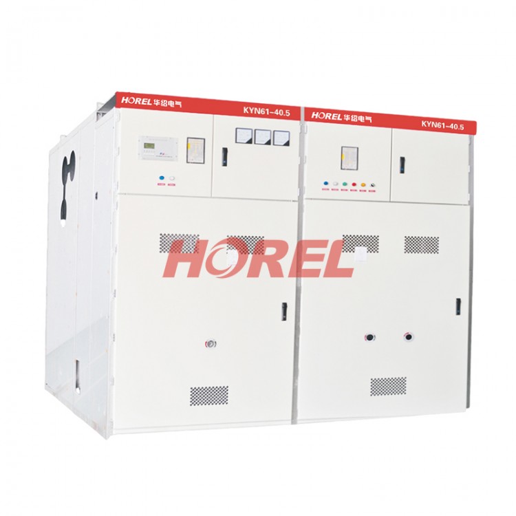
Product Overview
The KYN61-40.5D type armored withdrawable AC metal-enclosed switchgear (hereinafter referred to as "switchgear") features the use of ZN8540.5G vacuum circuit breakers and VB2 type spring-operated mechanisms with full insulation inside the cabinet. The cabinet is assembled with aluminum-zinc coated steel plates, enhancing the fit precision between the mobile panel and the cabinet, making it easy to slide in and out, and highly interchangeable. It boasts an attractive appearance, comprehensive solutions, and ensures safe and reliable operation.
This product is designed for use in a 35kV three-phase AC 50Hz power system, serving as a distribution room for power plants, sub-stations, and industrial and mining enterprises to receive and distribute electrical energy, featuring control, protection, and monitoring functions.
This product complies with the following standards: GB3906 "AC Metal-Enclosed Switchgear for 3.6~40.5KV", GB/T11022 "Technical Requirements for the Common Technology of High-Voltage Switchgear and Control Equipment", DL/T404 "Technical Conditions for Ordering AC High-Voltage Switchgear", and IEC298 "AC Metal-Enclosed Switchgear and Control Equipment for Rated Voltage above 1kV and up to 52kV".
Normal operating conditions
Ambient air temperature: -159°C to +409°C.
2. Altitude: 1000m and below.
3. Humidity Conditions:
The average daily value does not exceed 95%, and the average daily vapor pressure does not surpass 22 KPa.
The monthly average does not exceed 90%, and the monthly average vapor pressure does not exceed 1.8 KPa.
4. Earthquake Intensity: Not exceeding 8 degrees
5. No areas with corrosive or flammable gases, or other obvious contaminants.
Note: For usage beyond the normal conditions mentioned, customers may negotiate with our company.
Technical Specifications
| Name | Unit | Data |
| Rated Voltage | kV | 40.5 |
| Rated Current | Main busbar rated current | A | 630、1250、1600、2000 |
| Rated Current for Circuit Breakers | A | 630、1250、1600、2000 |
| Rated Insulation Level | 1 minute resistance to electrical porcelain, intermittent between electrodes | kV | 95/110 |
| Withstand voltage (peak) to lightning impulse, between electrodes, between electrode and ground/ between gaps | kV | 185/215 |
| Auxiliary circuit, control circuit's power frequency withstand voltage | 1min | 2000 |
| Rated Frequency | Hz | 50 |
| Rated short-circuit breaking current | kA | 20、25、31.5 |
| Rated short-time withstand current; rated short-duration current | kA/4s | 20、25、31.5 |
| Rated values withstand current | KA
kA | 50、63、80 |
| Rated short-circuit breaking current | 50、63、80 |
| Rated Voltage of Control Loop |
| V | Dc:110 200,AC: 110 220 |
| Protection Level | Switchgear Enclosure |
| IP4x |
| Partition (with door open) |
| IP2x |
| Dimensions (Width x Depth x Height) | mm | 1400x2800x2600 |
Structural Features
This product is divided into two main parts: the cabinet and the handcart. The cabinet is made by bending steel plates, coated with plastic spray, and assembled with bolts. It can be divided into four sections based on functional features: busbar compartment, relay instrument room, handcart room, cable room, and busbar room, which are separated by grounded metal partitions. The protection grade of the cabinet shell is IP4X; when the door of the handcart room is open, the protection grade is IP2X.
This switchgear offers a comprehensive circuit scheme including cable in and out lines, overhead in and out lines, busbar interconnections, isolation, voltage transformers, lightning arresters, and more. The busbars are equipped with composite insulation, with insulating sleeves made from flame-retardant materials for phase separation and connections. Adjacent cabinets for the main busbars are separated by busbar sleeves, effectively preventing accidents from spreading and also providing auxiliary support for the main busbars. The cable voids are fitted with earthing switches and overvoltage protection devices.
The contact box is equipped with a metal gate that automatically opens during the movement of the switchgear from the disconnected test position to the working position, and closes automatically when moving in the opposite direction, effectively isolating from high voltage. The interlock between the main switch, switchgear, grounding switch, and cabinet door is all adopted with a mandatory mechanical locking method, meeting the requirements of the "Five Preventive" functions. The circuit breaker switchgear uses a screw-driven propulsion mechanism with a slip clutch. The screw nut propulsion mechanism allows easy operation to move the switchgear between the test and working positions. The self-locking nature of the screw nut ensures reliable locking of the switchgear in the working position, preventing accidental movement caused by electromotive force and potential accidents. The overrunning clutch operates when the switchgear moves back to the test position and to the working position, automatically disengaging the operating shaft from the screw shaft for free rotation, preventing incorrect operation from damaging the propulsion mechanism. Other switchgear uses a lever propulsion mechanism. The test working position has a positioning pin for locking.
Ordering Instructions
1. Main circuit scheme number, purpose, single-line system diagram, arrangement diagram, and power distribution room layout.
2. Auxiliary circuit wiring diagram, terminal layout.
3. Model, specifications, and quantity of electrical components within the switchgear.
4. Requirements for control, measurement, and protection functions of switching equipment, as well as for other interlocking and automatic devices.
5. If busbars are required between switchgear or at the incoming line cabinet, please provide specific data such as the rated current carrying capacity of the busbar bridge, the span of the busbar bridge, and the height above ground.
6. When requiring accessories or spare parts, specify the type and quantity.
7. Switchgear for use in special environmental conditions should be specified in detail at the time of ordering.

 HR-CT1 Three-Phase Multi-functional Metering and Distribution Box
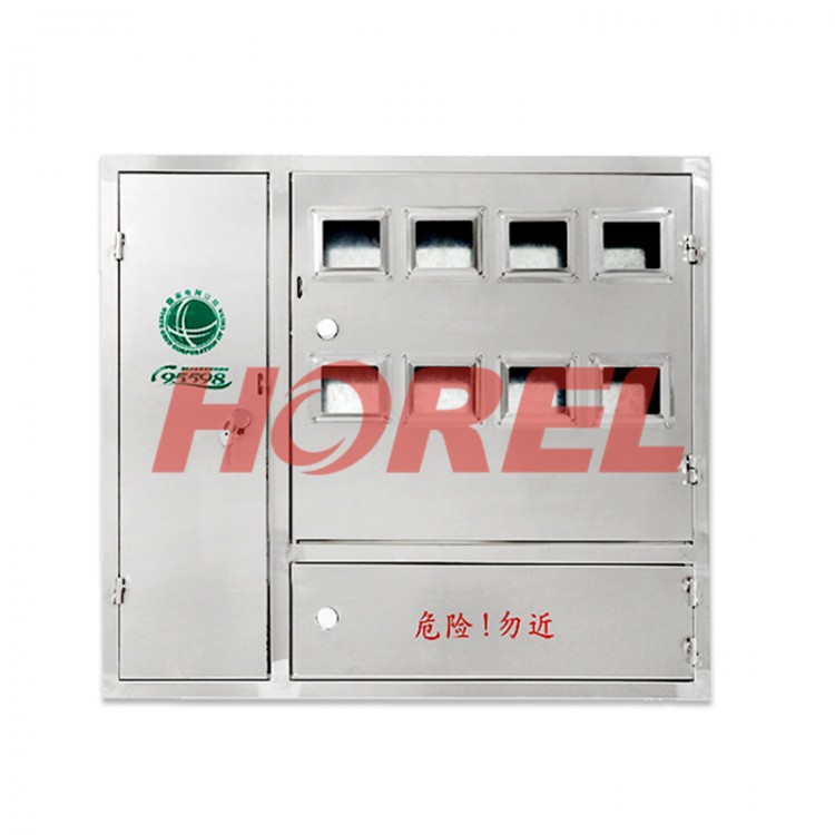 Stainless Steel Electric Meter Box Series Enclosures
 XGN17-40.5 Fixed Type High-Voltage Switchgear in Box Type

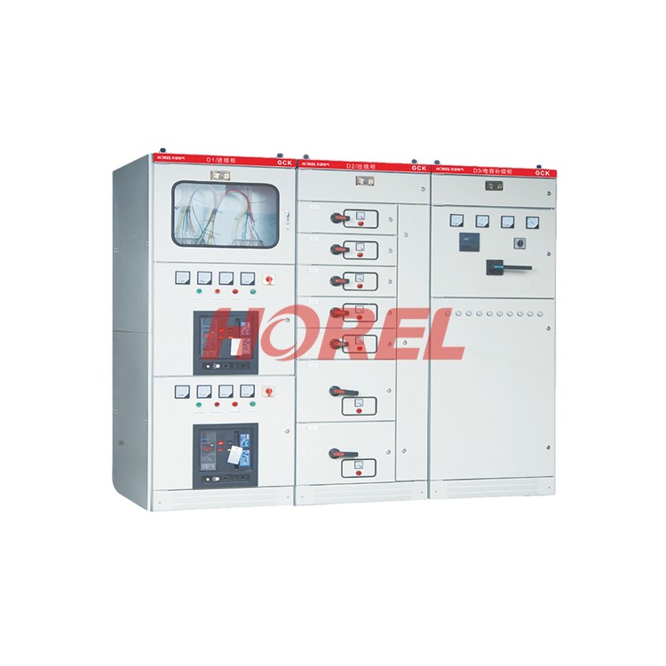 GCK Low-voltage Extraction-type Switchgear
 Two-phase one-meter transformer-type energy metering cabinet
 Single-phase, single-metering slot energy metering box
 Single-phase 14-slot cabinet (card type)