
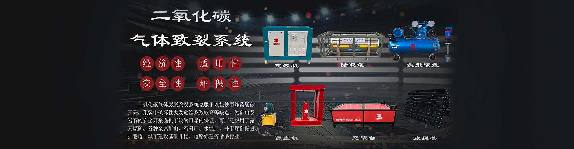
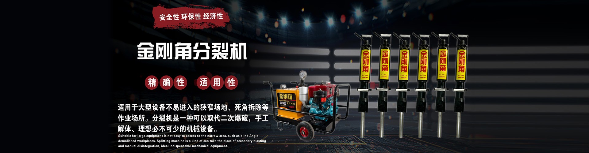


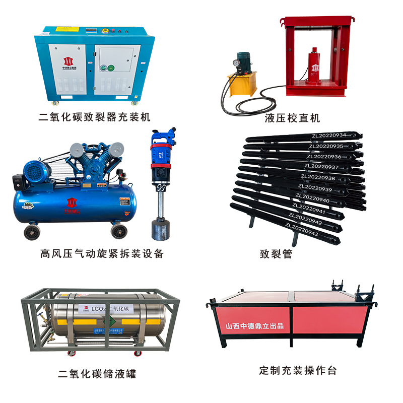
详情描述
Illustration of an invention based on carbon dioxide blasting technology.
This is a schematic illustration of perforation fracturing based on carbon dioxide blasting technology.
Hole-making bombs, hole-making racks, cutting slices, pressure gas detonators, activators, liquid storage pipes, thermal insulation layers, pistons, energy release heads, bullet exit ports, liquid filling ports, drill pipes, casing, fracturing zones.
Specific implementation method
To clarify the objectives, technical solutions, and key points of the present invention, the following will further describe the implementation methods with reference to the attached drawings.
This invention provides an embodiment based on carbon dioxide fracturing technology, utilizing carbon dioxide fracturing as a secondary energy source in composite perforating techniques. It currently reduces the incompatibility used in composite perforating, minimizing the likelihood of accidents during fracturing operations. The high pressure and strong seam-forming capability of carbon dioxide fracturing can effectively create fractures, which is significant for advancing the development of composite perforating technology and for oil, gas, and geothermal exploitation.
Please refer to, the embodiment of this invention provides a carbon dioxide fracturing technology, including a liquid storage tube and a perforation frame.
The liquid storage tube is equipped with a piston for sealing, which has a filling port. The bottom of the piston features an activator, the top of which is fixed to the bottom of the piston. The activator extends downward along the axis of the storage tube. The activator is electrically connected to the outside. The lower tube mouth of the storage tube has a sealing energy release head, which contains a cutting blade. The space between the piston and the energy release head within the storage tube is used for filling and releasing carbon dioxide. The storage tube is fitted with a pressure gas exploder, which is mounted on the inner wall of the storage tube.
The lower end of the fluid storage tube is connected to the perforation frame, which is internally equipped with multiple perforation charges arranged sequentially. The number of perforation charges can be designed according to the actual construction requirements. In this embodiment, two perforation charges are set up. Each perforation charge on the perforation frame is equipped with an ejection orifice in front, extending along the gap between the energy dissipation head and the inner wall of the fluid storage tube and connected to the pressure gas exploder. The fluid storage tube is filled with liquid carbon dioxide, which is vaporized by the activator. When the pressure inside the fluid storage tube rises to a predetermined value, the pressure gas exploder is triggered, igniting the explosive perforation charges. All the perforation charges are ejected to form perforation cavities in the formation rock mass. The outer wall of the fluid storage tube is insulated to effectively prevent external heat from conducting into the tube, causing the carbon dioxide inside to heat up. The continuous heating by the activator causes the pressure inside the fluid storage tube to rise until the shear slice breaks the energy dissipation head, thus connecting the fluid storage tube to the perforation frame. The high-pressure carbon dioxide gas inside the fluid storage tube is then ejected through the ejection orifices, impacting the perforation cavities to form a fracturing zone.
Please refer to the following usage of perforation fracturing with carbon dioxide fracturing technology as mentioned above:
Based on the strength of the rock, solidified concrete, and casing penetrated by the pre-shot boreholes, determine the penetration strength and depth of the shot holes, as well as the fluid volume and peak pressure for the CO2 blasting.
Load the radioactive perforating bullet into the perforating frame, open the filling port to fill liquid carbon dioxide into the storage tube until the preset filling volume is reached, then close the filling port and inspect the operational performance of all parts.
Connect the fluid storage tube to the bottom of the drill pipe, lower it into the wellbore through the casing until it reaches the target layer, adjust the direction of the ejection port, and align it with the predetermined perforation location.
Actuator, heats the liquid carbon dioxide within the storage tube, and upon the tube's pressure rising to the set value, which should be less than the peak pressure, triggers the pressure gas exploder, ignites it, and blasts all perforating guns to perforate, impacting the casing, concrete, and formation, creating perforation cavities.
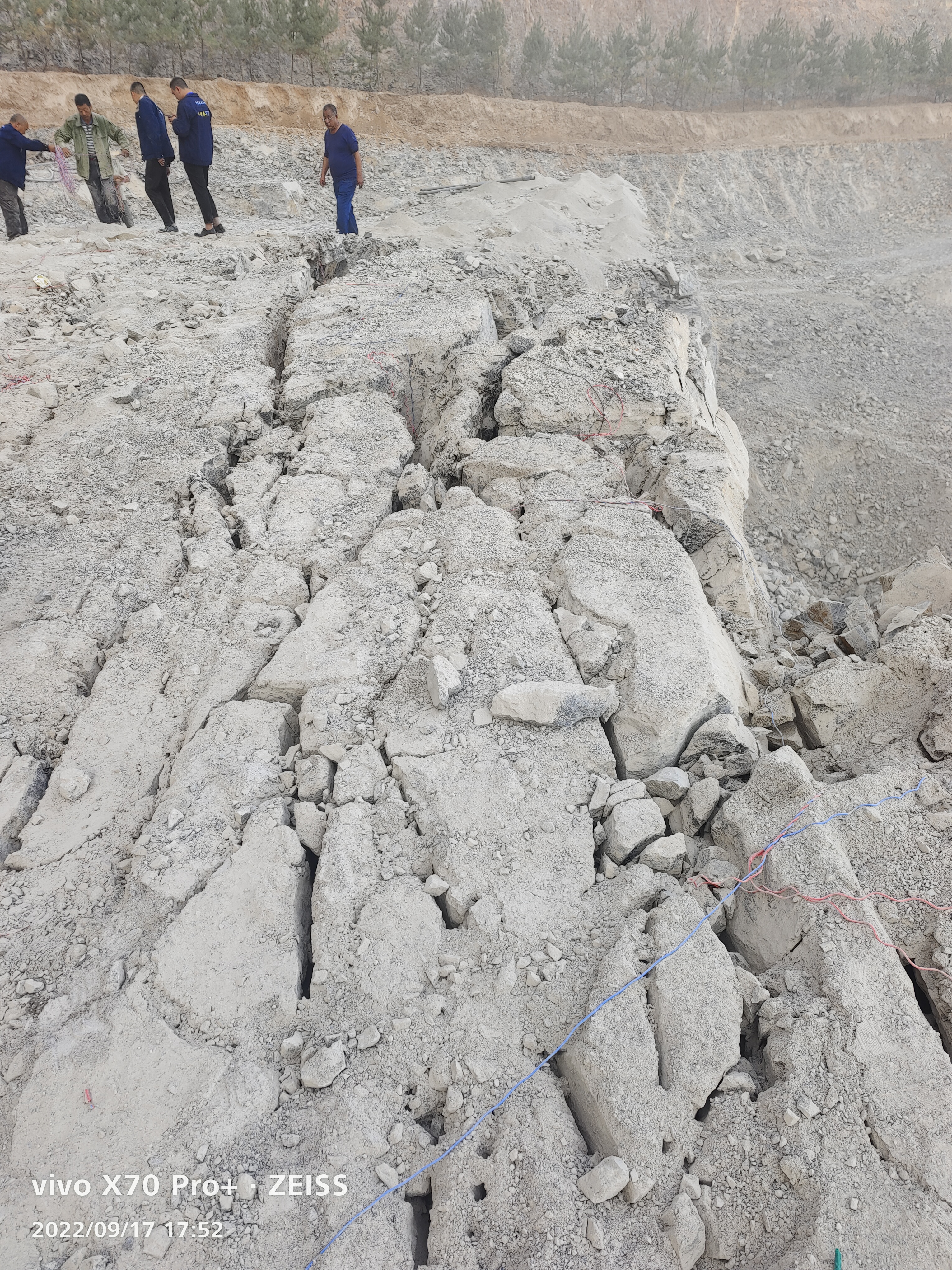
As the pressure inside the storage tube continues to rise to the peak pressure, the cutting slice ruptures, causing the pressure relief head to open. High-pressure carbon dioxide gas is instantaneously ejected from the exit, acting on the target layer rock mass within the perforation cavity, causing the rock mass to fracture and create fissures, forming a fracturing zone.
Monitor the fracturing operation's effectiveness, retrieve the device to the surface, reload perforating charges into the perforating架, fill the liquid CO2 into the storage tube, and perform the perforating fracturing again until the oil and gas extraction requirements are met.
Static blasting technology - Detailed explanation of CO2 blasting, gas blasting
Carbon dioxide blasting originated in the 1950s, began to develop in the U.S. in the 1980s, primarily developed for coal mining operations in high-gas mines to prevent explosion accidents caused by flames from blasting. By 2015, with the advancement of technology, domestic carbon dioxide manufacturers emerged gradually (with key components still imported, and slightly higher domestic failure rates), but they are currently not fully mature, still in a phase of continuous growth and development.
Currently, although there have been technological breakthroughs in domestic CO2 blasting construction in China, there is still a long way to go. Many technical improvements and enhancements are needed. The blasting output lags significantly compared to traditional blasting methods. Additionally, the operation process is more complex when compared to using hydraulic splitting equipment under the same non-blasting conditions, and the interval for recycling is longer.
The principle of carbon dioxide blasting
Carbon dioxide gas can be converted into a liquid state under high pressure. It is then compressed into a cylindrical container (blast tube) using a high-pressure pump. The container is fitted with a membrane, a bursting disc, a heat-conducting rod, and a sealing ring, and the preparation for the blast is complete once the alloy cap is tightened. Carry the blast tube and the power cable to the blast site, insert it into the drilled hole and secure it, then connect the power supply. When a microcurrent passes through the high-conductivity rod, it generates high heat to pierce the membrane, instantly vaporizing the liquid carbon dioxide. This rapid expansion produces a high-pressure shock wave that automatically opens the pressure relief valve. Utilizing the high pressure generated by the rapid expansion of the liquid carbon dioxide as it vaporizes, the rock mass is fractured.
Advantages of Carbon Dioxide Blasting:
1. No destructive vibrations or short waves during the blasting process, dust reduction, minimal impact on the surrounding environment.
2. Suitable for complex working environments, including coal mines and mining areas.
3. Carbon dioxide gas is readily available for purchase, with some equipment being reusable.
4. Multiple blasting tubes can be connected in parallel simultaneously, resulting in a greater blasting power and larger rock fragments after blasting.
Disadvantages of carbon dioxide blasting:
1. Low efficiency: The process is overly complicated, and we can't explode it several times a day. The more steps, the higher the chance of issues. Such as filling, wiring, sealing holes, etc.
2. Airface Requirement: Effective only when utilizing the airface; deep excavation sites or poor overhead work areas are not suitable.
3. Low output: Unable to achieve multi-row blasting, resulting in the number of blast tubes per single blast not being suitable for more than two rows; one row would cause jamming or damage to the blast tubes.
4. High cost: The activator used is single-use, and even at low production volumes, it results in high blasting costs.
5. High requirements: The filling process of blast tubes and on-site construction are both complex, with high demands on borehole quality.
6. Noise and: Although the explosive vibration force is not great, the sound is relatively prominent. If there are residential buildings and structures in the surrounding area, it is advisable to seek permission from the local authorities and environmental protection department first.
Zhongde Dingli offers a carbon dioxide charging structure, including a first-stage carbon dioxide blasting, the protective device, a second-stage carbon dioxide blasting, and the plug mud, wherein the first-stage and second-stage carbon dioxide blastings are connected to the starting mechanism, and the first-stage and second-stage carbon dioxide blastings are initiated sequentially through the starting mechanism.


